Info
Unless specified, all values in this section are hexadecimal values.
Tip
Robotiq suggests using the Robotiq User Interface test software to explore the various features of the Gripper, like object detection and force control.
Since the Robotiq 2-Finger has its own embedded controller, high-level commands, such as "Go to requested position" are used to control it.
Info
The operator can:
Control using registers
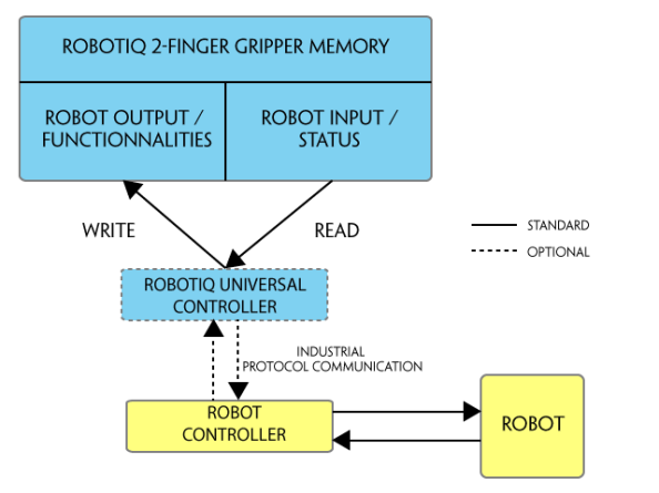
The Gripper has an internal memory that is shared with the robot controller. One part of the memory is for the robot output; gripper functionalities. The other part of the memory is for the robot input; gripper status. Two types of actions can then be done by the robot controller :
The Gripper Register Mapping section will map the different registers used to control the Gripper or to read its status while the Robot Output Registers & Functionalities section will detail the output (write) register functions, and the Robot Input Registers & Status section will detail the input (read) register status. The figure below is a representation of the memory and the control logic of the Gripper.
Fig. 4-1: 2-Finger control logic overview
Register mapping
Caution
Byte numeration starts at zero and not at 1 for the functionalities and status registers.
|
Register |
Robot Output / Functionalities |
Robot Input / Status |
|---|---|---|
|
Byte 0 |
ACTION REQUEST |
GRIPPER STATUS |
|
Byte 1 |
RESERVED |
RESERVED |
|
Byte 2 |
RESERVED |
FAULT STATUS |
|
Byte 3 |
POSITION REQUEST |
POS REQUEST ECHO |
|
Byte 4 |
SPEED |
POSITION |
|
Byte 5 |
FORCE |
CURRENT |
|
Byte 6 to 15 |
RESERVED |
RESERVED |
Table 4-1: Registers of the 2-Finger Gripper.
Register: ACTION REQUEST
Address: Byte 0
|
Bits |
7 |
6 |
5 |
4 |
3 |
2 |
1 |
0 |
|---|---|---|---|---|---|---|---|---|
|
Symbols |
Reserved |
rARD |
rATR |
rGTO |
Reserved |
rACT |
||
rACT: First action to be made prior to any other actions, rACT bit will activate the Gripper. Clear rACT to reset the Gripper and clear fault status.
Warning
When setting rACT to one, the Gripper will begin movement to complete its auto-calibration feature.
Info
Power loss will set rACT; rACT bit must then be cleared, then set to allow operation of the Gripper.
Caution
rACT bit must stay on afterwards for any other action to be performed.
rGTO: The "Go To" action moves the Gripper fingers to the requested position using the configuration defined by the other registers, rGTO will engage motion while byte 3, 4 and 5 will determine aimed position, force and speed. The only motions performed without the rGTO bit are activation and automatic release routines.
rATR: Automatic Release routine action slowly opens the Gripper fingers until all motion axes reach their mechanical limits. After all motion is completed, the Gripper sends a fault signal and needs to be reactivated before any other motion is performed. The rATR bit overrides all other commands excluding the activation bit (rACT).
Caution
The automatic release is meant to disengage the Gripper after an emergency stop of the robot.
The automatic release is not intended to be used under normal operating conditions.
Automatic release will require rACT to be cleared (rACT == 0) then set (rACT == 1).
rARD: Auto-release direction. When auto-releasing, rARD commands the direction of the movement. The rARD bit should be set prior to or at the same time as the rATR bit, as the motion direction is set when the auto-release is initiated.
Register: GRIPPER OPTIONS
Address: Byte 1
Register: GRIPPER OPTIONS 2
Address: Byte 2
|
Bits |
7 |
6 |
5 |
4 |
3 |
2 |
1 |
0 |
|---|---|---|---|---|---|---|---|---|
|
Symbol |
Reserved |
|||||||
Register: POSITION REQUEST
Address: Byte 3
|
Bits |
7 |
6 |
5 |
4 |
3 |
2 |
1 |
0 |
|---|---|---|---|---|---|---|---|---|
|
Symbol |
rPR |
|||||||
This register is used to set the target position for the Gripper's fingers. The positions 0x00 and 0xFF correspond respectively to the fully opened and fully closed mechanical stops. For detailed finger trajectory, please refer to the Specifications section.
Info
The activation feature of the Robotiq Adaptive Gripper will allow the Gripper to adjust to any fingertips. No matter what is the size and shape of the fingertips used, 0 will always be fully opened and 255 fully closed, with a quasi-linear relationship between 0 and 255.
Register: SPEED
Address: Byte 4
|
Bits |
7 |
6 |
5 |
4 |
3 |
2 |
1 |
0 |
|---|---|---|---|---|---|---|---|---|
|
Symbol |
rSP |
|||||||
This register is used to set the Gripper closing or opening speed in real time, however, setting a speed will not initiate a motion.
Register: FORCE
Address: Byte 5
|
Bits |
7 |
6 |
5 |
4 |
3 |
2 |
1 |
0 |
|---|---|---|---|---|---|---|---|---|
|
Symbol |
rFR |
|||||||
The force setting defines the final gripping force for the Gripper. The force will fix the maximum current sent to the motor while in motion. If the current limit is exceeded, the fingers stop and trigger an object detection notification. Please refer to the Robot Input Registers & Status section for details on force control.
Info
Register bytes 6 to 15 are reserved and should be set to zero.
Register: GRIPPER STATUS
Address: Byte 0
|
Bits |
7 |
6 |
5 |
4 |
3 |
2 |
1 |
0 |
|---|---|---|---|---|---|---|---|---|
|
Symbols |
gOBJ |
gSTA |
gGTO |
Reserved |
gACT |
|||
gACT: Activation status, echo of the rACT bit (activation bit).
gGTO: Action status, echo of the rGTO bit (go to bit).
gSTA: Gripper status, returns the current status & motion of the Gripper fingers.
gOBJ: Object detection status, is a built-in feature that provides information on possible object pick-up. Ignore if gGTO == 0.
Caution
In some circumstances object detection may not detect an object even if it is successfully grasped. For example, picking up a thin object in a fingertip grasp may be successful without object detection occurring. For such reasons, use this feature with caution. In these applications when the "Fingers are at requested position" status of register gOBJ, this is sufficient to proceed to the next step of the routine.
Tip
Checking for the correct position of the fingers (byte 4), as well as object detection (byte 0, bit 6 & 7) before proceeding to the next step of a routine is a more reliable method than object detection or finger position alone.
Register: RESERVED
Address: Byte 1
|
Bits |
7 |
6 |
5 |
4 |
3 |
2 |
1 |
0 |
|---|---|---|---|---|---|---|---|---|
|
Symbol |
Reserved |
|||||||
Register: FAULT STATUS
Address: Byte 2
|
Bits |
7 |
6 |
5 |
4 |
3 |
2 |
1 |
0 |
|---|---|---|---|---|---|---|---|---|
|
Symbols |
kFLT |
gFLT | ||||||
gFLT: Fault status returns general error messages that are useful for troubleshooting. Fault LED (red) is present on the Gripper chassis, LED can be blue, red or both and be solid or blinking.
Minor faults (LED continuous red)
Major faults (LED blinking red/blue) - Reset is required (rising edge on activation bit rACT needed).
Info
While booting, status LED will be solid blue / red.
kFLT : See your optional Controller Manual (input registers & status).
Register: POSITION REQUEST ECHO
Address: Byte 3
|
Bits |
7 |
6 |
5 |
4 |
3 |
2 |
1 |
0 |
|---|---|---|---|---|---|---|---|---|
|
Symbol |
gPR |
|||||||
gPR: Echo of the requested position for the Gripper, value between 0x00 and 0xFF.
Register: POSITION
Address: Byte 4
|
Bits |
7 |
6 |
5 |
4 |
3 |
2 |
1 |
0 |
|---|---|---|---|---|---|---|---|---|
|
Symbol |
gPO |
|||||||
gPO: Actual position of the Gripper obtained via the encoders, value between 0x00 and 0xFF.
Register: CURRENT
Adress: Byte 5
|
Bits |
7 |
6 |
5 |
4 |
3 |
2 |
1 |
0 |
|---|---|---|---|---|---|---|---|---|
|
Symbol |
gCU |
|||||||
gCU: The current is read instantaneously from the motor drive, value between 0x00 and 0xFF, approximate current equivalent is 10 * value read in mA.
Tip
Built-in features like object detection and force control use the finger's electrical current readings. The user does not need to create these features.
As stated in previous sections, object picking is done via a simple "Go To" command, rGTO bit calls for movement, while rPR byte is the aimed position, rSP and rFR will be the desired speed and force settings respectively. This section describes key features in object picking applications:
The 2-Finger Gripper gripping force is controlled via the rFR byte (refer to the Gripper Register Mapping section).The Gripper behavior will change according to the rFR force requested.
The table below shows the expected applied force according to the payload material hardness, speed setting rSP and force setting rFR. All tests were done with the 2-Finger Gripper with firmware GC3-1.3.9. Data was obtained with a Load Cell from Phidget, S Type, model 3138.
|
FINGER PAD |
PAYLOAD |
MEASURED FORCE MIN / MAX (N) |
|||
|---|---|---|---|---|---|
|
TYPE |
HARDNESS |
TYPE |
HARDNESS |
2-Finger 85 |
2-Finger 140 |
|
Steel 4340 |
220 HV |
Steel 4340 |
220 HV3 |
25 - 220 |
15 - 120 |
|
Aluminium 60611 |
95 HV |
Aluminium 6061 |
95 HV |
25 - 220 |
15 - 120 |
|
Aluminium 60611 |
95 HV |
Silicone (TIP-204)2 |
60 A Durometer |
25 - 220 |
15 - 120 |
|
Aluminium 60611 |
95 HV |
Silicone rubber |
40 A Durometer4 |
25 - 155 |
15 - 100 |
|
Aluminium 60611 |
95 HV |
Neoprene rubber |
10 A Durometer |
25 - 115 |
15 - 75 |
|
Aluminium 60611 |
95 HV |
Polyurethane rubber |
30 OO Durometer |
25 - 115 |
15 - 75 |
1 Available with V-Groove fingertip AGC-TIP-205-0085 / AGC-TIP-421-140.
2 Available with flat silicone fingertip AGC-TIP-204-085 / AGC-TIP-420-140.
3 HV refers to Vickers hardness test.
4 Durometer refers to Shore durometer hardness, scale A or scale OO.
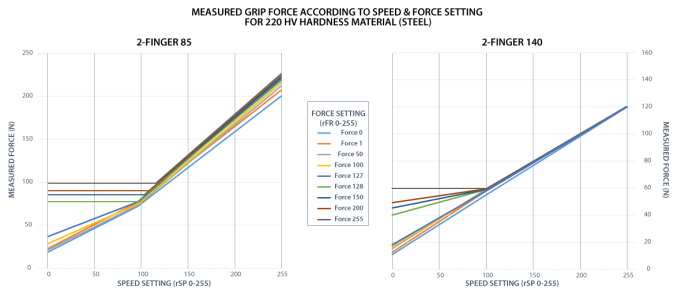
Fig. 4-2: grasp force on hardness 220 HV (4340 annealed carbon steel).
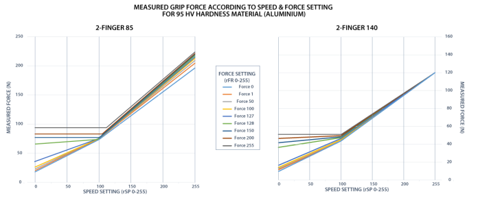
Fig. 4-3: grasp force on hardness 95 HV (6061-T6 aluminium).
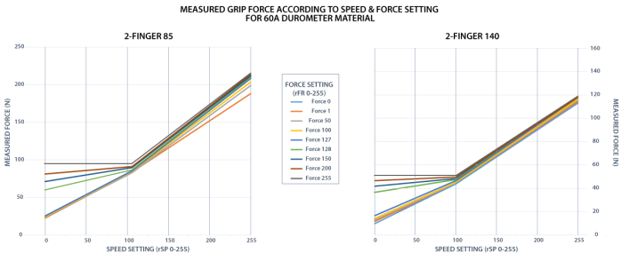
Fig. 4-4: grasp force on hardness 60A (silicone).
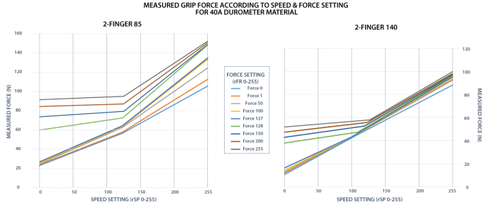
Fig. 4-5: grasp force on hardness 40 A (silicone).
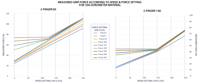
Fig. 4-6: grasp force on hardness 10 A (neoprene).
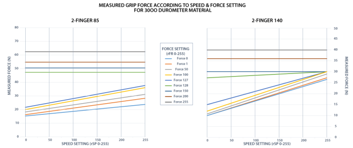
Fig. 4-7: grasp force on hardness 30 OO (polyurethane).
Re-grasp feature is a built-in feature meant to prevent object lost due to slipping or inaccurate initial grip. The Re-grasp feature will allow the Gripper to initiate movement when an object is slipping or dropped. When Re-grasping, the Gripper will attempt to close until it reaches the position (rPR) request.
Info
Feature is off at force request rFR = 0, otherwise it is on.
Info
While your initial settings for force and speed are not used for Re-grasp, they will never be exceeded to prevent damaging the object grasped.
Info
The rOBJ status is cleared when a motion is detected.
When the Gripper grabs an object, gOBJ status will allow you to know if object retention was successful. This is a built-in feature for the 2-Finger Grippers meant to be used by the robot controller (or PLC) commanding the overall application. The Object detection feature will change the gOBJ status and can be used inside your robot program. As stated in the previous section:
gOBJ: Only valid if gGTO = 1.
Object detection exemple:
Object lost example:
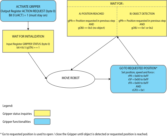
Fig. 4-8: Example of the 2-Finger control logic with associated registers.
The Gripper can be controlled by Modbus RTU directly with RS485-RS232 using the ACC-ADT-RS232-RS485, or over USB using the ACC-ADT-USB-RS485. This section is intended to provide guidelines for setting up a Modbus scanner that will adequately communicate with the Gripper.
For a general introduction to Modbus RTU and for details regarding the CRC algorithm, the reader is invited to read the Modbus over serial line specification and implementation guide available at: http://www.modbus.org/docs/Modbus_over_serial_line_V1_02.pdf.
For debugging purposes, the reader is also invited to download one of many free Modbus scanners such as the CAS Modbus Scanner from Chipkin Automation Systems available at: http://www.store.chipkin.com/products/tools/cas-modbus-scanner.
Info
Modbus RTU is a communication protocol based on a Big Endian byte order. Therefore, the 16-bit register addresses are transmitted with the most significant byte first. However, the data port is in the case of Robotiq products based on the Little Endian byte order. As such, the data parts of Modbus RTU messages are sent with the less significant byte first.
Tip
Modbus RTU specification and details can be found at www.modbus.org.
The following table describes the connection requirements for controlling the Gripper using the Modbus RTU protocol.
|
PROPRIETY |
VALUE |
|---|---|
|
Physical Interface |
RS-4851 |
|
Baud Rate2 |
115,200 bps |
|
Data Bits |
8 |
|
Stop Bit2 |
1 |
|
Parity2 |
None |
|
Supported Functions |
Read Holding Register (FC03) Read Input Registers (FC04) Preset Multiple Register (FC16) Master read & write multiple registers (FC23) |
|
Exception Responses |
Not supported |
|
Slave ID2 |
0x0009 (9) |
|
Robot Output / Gripper Input First Register |
0x03E8 (1000) |
|
Robot Input / Gripper Output First Register |
0x07D0 (2000) |
1 Various converters are available in the Spare parts section.
2 These parameters can be adjusted using the Robotiq User Interface.
Each register (word - 16 bits) of the Modbus RTU protocol is composed of 2 bytes (8 bits) from the Gripper. The first Gripper output Modbus register(0x07D0) is composed from the first 2 Robotiq Gripper bytes (byte 0 and byte 1).
Info
200 Hz is the usual speed when commanding / reading from the Robotiq Gripper. It is therefore recommended to send commands with a minimum delay of 5 ms between them.
Info
Maximum baud rate of ACC-ADT-USB-RS485 is 115200 bps.
120 Ohms termination resistor is already present on the converter.
Function code 03 (FC03) is used for reading the status of the Gripper (robot input). Examples of such data are Gripper status, object status, finger position, etc.
Example of FC03 Read function:
This message asks for register 0x07D0 (2000) and register 0x07D1 (2001) which contains Gripper Status, Object Detection, Fault Status and Position Request Echo.
Request is: 09 03 07 D0 00 02 C5 CE
|
Bits |
Description |
|---|---|
|
09 |
SlaveID |
|
03 |
Function Code 03 (Read Holding Registers) |
|
07D0 |
Address of the first requested register |
|
0002 |
Number of registers requested (2) |
|
C5CE |
Cyclic Redundancy Check (CRC) |
Response is: 09 03 04 E0 00 00 00 44 33
|
Bits |
Description |
|---|---|
|
09 |
SlaveID |
|
03 |
Function Code 03 (Read Holding Registers) |
|
04 |
Number of data bytes to follow (2 registers x 2 bytes/register = 4 bytes) |
|
E000 |
Content of register 07D0 |
|
0000 |
Content of register 07D1 |
|
4433 |
Cyclic Redundancy Check (CRC) |
Function code 04 (FC04) is used for requesting the status of the Gripper's analog input register. Examples of such data are Gripper status, object status, finger position, etc.
Example of FC04 read function:
This message asks for register 0x07D0 (2000) and register 0x07D1 (2001) which contains Gripper Status, Object Detection, Fault Status and Position Request Echo.
Request is: 09 04 07 D0 00 02 C5 CE
|
Bits |
Description |
|---|---|
|
09 |
SlaveID |
|
04 |
Function Code 03 (Read Holding Registers) |
|
07D0 |
Address of the first requested register |
|
0002 |
Number of registers requested (2) |
|
700E |
Cyclic Redundancy Check (CRC) |
Response is: 09 04 04 E0 00 00 00 44 33
|
Bits |
Description |
|---|---|
|
09 |
SlaveID |
|
04 |
Function Code 04 (Read Holding Registers) |
|
04 |
Number of data bytes to follow (2 registers x 2 bytes/register = 4 bytes) |
|
E000 |
Content of register 07D0 |
|
0000 |
Content of register 07D1 |
|
4584 |
Cyclic Redundancy Check (CRC) |
Function code 16 (FC16) is used to activate functionalities of the Gripper (robot output). Examples of such data are action request, speed, force, etc.
Example of setting multiple registers FC16:
This message requests to set position request, speed and force of the Gripper by setting register 0x03E9 (1002) and 0x03EA.
Request is: 09 10 03 E9 00 02 04 60 E6 3C C8 EC 7C
|
Bits |
Description |
|---|---|
|
09 |
SlaveID |
|
10 |
Function Code 16 (Preset Multiple Registers) |
|
03E9 |
Address of the first register |
|
0002 |
Number of registers written to |
|
04 |
Number of data bytes to follow (2 registers x 2 bytes/register = 4 bytes) |
|
60E6 |
Value written to register 0x03E9 |
|
3CC8 |
Value written to register 0x03EA |
|
EC7C |
Cyclic Redundancy Check (CRC) |
Response is: 09 10 03 E9 00 02 91 30
|
Bits |
Description |
|---|---|
|
09 |
SlaveID |
|
10 |
Function Code 16 (Preset Multiple Registers) |
|
03E9 |
Address of the first register |
|
0002 |
Number of written registers |
|
9130 |
Cyclic Redundancy Check (CRC) |
Function code 23 (FC23) is used for reading the status of the Gripper (robot input) and activating functionalities of the Gripper (robot output) simultaneously. Examples of such data are Gripper status, object status, finger position, etc. Action requests are speed, force, etc.
Example of reading and writing multiple registers FC23:
This message reads registers 0x07D0 (2000) and 0x07D1 (2001), which contains Gripper Status, Object Detection, Fault Status and Position Request Echo. It also sets the position request, speed and force of the Gripper by writing to registers 0x03E9 (1001) and 0x03EA (1002).
Request is: 09 17 07 D0 00 02 03 E9 00 02 04 00 E6 3C C8 2D 0C
|
Bits |
Description |
|---|---|
|
09 |
SlaveID |
|
17 |
Function Code 23 (read and write multiple registers) |
|
07D0 |
Address of the first requested register, read |
|
0002 |
Number of registers requested (2), read |
|
03E9 |
Address of the first register written to |
|
0002 |
Number of registers written to (3) |
|
04 |
Number of data bytes to follow (2 registers X 2 bytes/registers = 4 bytes) |
|
00E6 |
Value written to register 0x03E9 |
|
3CC8 |
Value written to register 0x03EA |
|
2D0C |
Cyclic Redundancy Check (CRC) |
Response is: 09 17 04 01 00 09 E6 F6 C1
|
Bits |
Description |
|---|---|
|
09 |
SlaveID |
|
17 |
Function Code 23 (read and write multiple registers) |
|
04 |
Number of data bytes to follow (2 registers x 2 bytes/register = 4 bytes) |
|
1000 |
Content of register 07D0 |
|
09E6 |
Content of register 07D1 |
|
F6C1 |
Cyclic Redundancy Check (CRC) |
Note that the content of the response might change depending on the Gripper's status.
This section depicts the example given in the Control Logic section when programmed using the Modbus RTU protocol. The example is typical of a pick and place application. After activating the Gripper, the robot is moved to a pick-up location to grasp an object. It moves again to a second location to release the grasped object.
Step 1: Activation Request ( clear and set rACT)
Request is (clear rAct): 09 10 03 E8 00 03 06 00 00 00 00 00 00 73 30
|
Bits |
Description |
|---|---|
|
09 |
SlaveID |
|
10 |
Function Code 16 (Preset Multiple Registers) |
|
03E8 |
Address of the first register |
|
0003 |
Number of registers written to |
|
06 |
Number of data bytes to follow (3 registers x 2 bytes/register = 6 bytes) |
|
0000 |
Value to write to register 0x03E9 (ACTION REQUEST = 0x01 and GRIPPER OPTIONS = 0x00): rACT = 1 for "Activate Gripper" |
|
0000 |
Value written to register 0x03EA |
|
0000 |
Value written to register 0x03EB |
|
7330 |
Cyclic Redundancy Check (CRC) |
Response is: 09 10 03 E8 00 03 01 30
|
Bits |
Description |
|---|---|
|
09 |
SlaveID |
|
10 |
Function Code 16 (Preset Multiple Registers) |
|
03E8 |
Address of the first register |
|
0003 |
Number of written registers |
|
0130 |
Cyclic Redundancy Check (CRC) |
Request is (set rAct): 09 10 03 E8 00 03 06 01 00 00 00 00 00 72 E1
|
Bits |
Description |
|---|---|
|
09 |
SlaveID |
|
10 |
Function Code 16 (Preset Multiple Registers) |
|
03E8 |
Address of the first register |
|
0003 |
Number of registers written to |
|
06 |
Number of data bytes to follow (3 registers x 2 bytes/register = 6 bytes) |
|
0100 |
Value to write to register 0x03E9 (ACTION REQUEST = 0x01 and GRIPPER OPTIONS = 0x00): rACT = 1 for "Activate Gripper" |
|
0000 |
Value written to register 0x03EA |
|
0000 |
Value written to register 0x03EB |
|
72E1 |
Cyclic Redundancy Check (CRC) |
Response is: 09 10 03 E8 00 03 01 30
|
Bits |
Description |
|---|---|
|
09 |
SlaveID |
|
10 |
Function Code 16 (Preset Multiple Registers) |
|
03E8 |
Address of the first register |
|
0003 |
Number of written registers |
|
0130 |
Cyclic Redundancy Check (CRC) |
Step 2: Read Gripper status until the activation is completed
Request is: 09 03 07 D0 00 01 85 CF
|
Bits |
Description |
|---|---|
|
09 |
SlaveID |
|
03 |
Function Code 03 (Read Holding Registers) |
|
07D0 |
Address of the first requested register |
|
0001 |
Number of registers requested (1) |
|
85CF |
Cyclic Redundancy Check (CRC) |
Response (if the activation IS NOT completed): 09 03 02 11 00 55 D5
|
Bits |
Description |
|---|---|
|
09 |
SlaveID |
|
03 |
Function Code 03 (Read Holding Registers) |
|
02 |
Number of data bytes to follow (1 register x 2 bytes/register = 2 bytes) |
|
1100 |
Content of register 07D0 (GRIPPER STATUS = 0x11, RESERVED = 0x00): gACT = 1 for "Gripper Activation", gSTA = 1 for "Activation in progress" |
|
55D5 |
Cyclic Redundancy Check (CRC) |
Response (if the activation IS completed): 09 03 02 31 00 4C 15
|
Bits |
Description |
|---|---|
|
09 |
SlaveID |
|
03 |
Function Code 03 (Read Holding Registers) |
|
02 |
Number of data bytes to follow (1 register x 2 bytes/register = 2 bytes) |
|
3100 |
Content of register 07D0 (GRIPPER STATUS = 0x31, RESERVED = 0x00): gACT = 1 for "Gripper Activation", gSTA = 3 for "Activation is completed" |
|
4C15 |
Cyclic Redundancy Check (CRC) |
Step 3: Move the robot to the pick-up location
Step 4: Close the Gripper at full speed and full force
Request is: 09 10 03 E8 00 03 06 09 00 00 FF FF FF 42 29
|
Bits |
Description |
|---|---|
|
09 |
SlaveID |
|
10 |
Function Code 16 (Preset Multiple Registers) |
|
03E8 |
Address of the first register |
|
0003 |
Number of registers written to |
|
06 |
Number of data bytes to follow (3 registers x 2 bytes/register = 6 bytes) |
|
0900 |
Value written to register 0x03E8 (ACTION REQUEST = 0x09 and GRIPPER OPTIONS = 0x00): rACT = 1 for "Activate Gripper", rGTO = 1 for "Go to Requested Position" |
|
00FF |
Value written to register 0x03E9 (GRIPPER OPTIONS 2 = 0x00 and POSITION REQUEST = 0xFF): rPR = 255/255 for full closing of the Gripper |
|
FFFF |
Value written to register 0x03EA (SPEED = 0xFF and FORCE = 0xFF): full speed and full force |
|
4229 |
Cyclic Redundancy Check (CRC) |
Response is: 09 10 03 E8 00 03 01 30
|
Bits |
Description |
|---|---|
|
09 |
SlaveID |
|
10 |
Function Code 16 (Preset Multiple Registers) |
|
03E8 |
Address of the first register |
|
0003 |
Number of written registers |
|
0130 |
Cyclic Redundancy Check (CRC) |
Step 5: Read Gripper status until the grasp is completed
Request is: 09 03 07 D0 00 03 04 0E
|
Bits |
Description |
|---|---|
|
09 |
SlaveID |
|
03 |
Function Code 03 (Read Holding Registers) |
|
07D0 |
Address of the first requested register |
|
0003 |
Number of registers requested (3) |
|
040E |
Cyclic Redundancy Check (CRC) |
Example of response if the grasp is not completed: 09 03 06 39 00 00 FF 0E 0A F7 8B
|
Bits |
Description |
|---|---|
|
09 |
SlaveID |
|
03 |
Function Code 03 (Read Holding Registers) |
|
06 |
Number of data bytes to follow (3 registers x 2 bytes/register = 6 bytes) |
|
3900 |
Content of register 07D0 (GRIPPER STATUS = 0x39, RESERVED = 0x00): gACT = 1 for "Gripper Activation", gGTO = 1 for "Go to Position Request" and gOBJ = 0 for "Fingers are in motion" |
|
00FF |
Content of register 07D1 (FAULT STATUS = 0x00, POSITION REQUEST ECHO = 0xFF): the position request echo tells that the command was well received and that the GRIPPER STATUS is valid. |
|
0E0A |
Content of register 07D2 (POSITION = 0x0E, FINGER CURRENT = 0x0A): the position is 14/255 and the motor current is 100mA (these values will change during motion) |
|
F78B |
Cyclic Redundancy Check (CRC) |
Example of response if the grasp is completed: 09 03 06 B9 00 00 FF BD 00 1D 7C
|
Bits |
Description |
|---|---|
|
09 |
SlaveID |
|
03 |
Function Code 03 (Read Holding Registers) |
|
06 |
Number of data bytes to follow (3 registers x 2 bytes/register = 6 bytes) |
|
B900 |
Content of register 07D0 (GRIPPER STATUS = 0xB9, RESERVED = 0x00): gACT = 1 for "Gripper Activation", gGTO = 1 for "Go to Position Request" and gOBJ = 2 for "Fingers have stopped due to a contact while closing" |
|
00FF |
Content of register 07D1 (FAULT STATUS = 0x00, POSITION REQUEST ECHO = 0xFF): the position request echo tells that the command was well received and that the GRIPPER STATUS is valid. |
|
BD00 |
Content of register 07D2 (POSITION = 0xBD, FINGER CURRENT = 0x00): the position is 189/255 (can be used to validate the size of the seized object) |
|
1D7C |
Cyclic Redundancy Check (CRC) |
Step 6: Move the robot to the release location
Step 7: Open the Gripper at full speed and full force
Request is: 09 10 03 E8 00 03 06 09 00 00 00 FF FF 72 19
|
Bits |
Description |
|---|---|
|
09 |
SlaveID |
|
10 |
Function Code 16 (Preset Multiple Registers) |
|
03E8 |
Address of the first register |
|
0003 |
Number of registers written to |
|
06 |
Number of data bytes to follow (3 registers x 2 bytes/register = 6 bytes) |
|
0900 |
Value written to register 0x03E8 (ACTION REQUEST = 0x09 and GRIPPER OPTIONS = 0x00): rACT = 1 for "Activate Gripper", rGTO = 1 for "Go to Requested Position" |
|
0000 |
Value written to register 0x03E9 (GRIPPER OPTIONS 2 = 0x00 and POSITION REQUEST = 0x00): rPR = 0/255 for full opening of the Gripper (partial opening would also be possible) |
|
FFFF |
Value written to register 0x03EA (SPEED = 0xFF and FORCE = 0xFF): full speed and full force |
|
7219 |
Cyclic Redundancy Check (CRC) |
Response is: 09 10 03 E8 00 03 01 30
|
Bits |
Description |
|---|---|
|
09 |
SlaveID |
|
10 |
Function Code 16 (Preset Multiple Registers) |
|
03E8 |
Address of the first register |
|
0003 |
Number of written registers |
|
0130 |
Cyclic Redundancy Check (CRC) |
Step 8: Read Gripper status until the opening is completed
Request is: 09 03 07 D0 00 03 04 0E
|
Bits |
Description |
|---|---|
|
09 |
SlaveID |
|
03 |
Function Code 03 (Read Holding Registers) |
|
07D0 |
Address of the first requested register |
|
0003 |
Number of registers requested (3) |
|
040E |
Cyclic Redundancy Check (CRC) |
Example of response if the opening is not completed: 09 03 06 39 00 00 00 BB 10 30 E0
|
Bits |
Description |
|---|---|
|
09 |
SlaveID |
|
03 |
Function Code 03 (Read Holding Registers) |
|
06 |
Number of data bytes to follow (3 registers x 2 bytes/register = 6 bytes) |
|
3900 |
Content of register 07D0 (GRIPPER STATUS = 0x39, RESERVED = 0x00): gACT = 1 for "Gripper Activation", gGTO = 1 for "Go to Position Request" and gOBJ = 0 for "Fingers are in motion" |
|
0000 |
Content of register 07D1 (FAULT STATUS = 0x00, POSITION REQUEST ECHO = 0x00): the position request echo tells that the command was well received and that the GRIPPER STATUS is valid. |
|
BB10 |
Content of register 07D2 (POSITION = 0xBB, FINGER CURRENT = 0x10): the position is 187/255 and the motor current is 160mA (these values will change during motion) |
|
30E0 |
Cyclic Redundancy Check (CRC) |
Example of response if the opening is completed: 09 03 06 F9 00 00 00 0D 00 56 4C
|
Bits |
Description |
|---|---|
|
09 |
SlaveID |
|
03 |
Function Code 03 (Read Holding Registers) |
|
06 |
Number of data bytes to follow (3 registers x 2 bytes/register = 6 bytes) |
|
F900 |
Content of register 07D0 (GRIPPER STATUS = 0xF9, RESERVED = 0x00): gACT = 1 for "Gripper Activation", gGTO = 1 for "Go to Position Request" and gOBJ = 3 for "Fingers are at requested position" |
|
0000 |
Content of register 07D1 (FAULT STATUS = 0x00, POSITION REQUEST ECHO = 0x00): the position request echo tells that the command was well received and that the GRIPPER STATUS is valid. |
|
0D00 |
Content of register 07D2 (POSITION = 0x0D, FINGER CURRENT = 0x00): the position is 13/255 (the fingers have reached their software limit) |
|
564C |
Cyclic Redundancy Check (CRC) |
Step 9: Loop back to step 3 if other objects have to be grasped.
|
Hardware Version |
TM Flow Version |
TM Gripper Component |
Robotiq RS232 Converter |
|---|---|---|---|
|
HW1, HW2, HW3 |
1.68 and later |
2F85_V004_XXX |
Compatible |
![]()
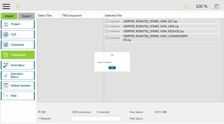
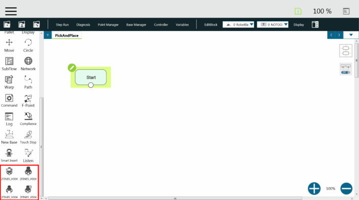
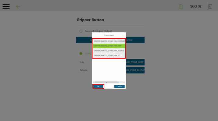
Here is the list of the current Robotiq Gripper TM Components to install on TM Robots:
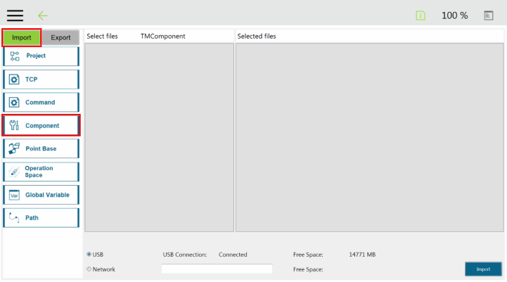
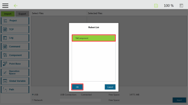
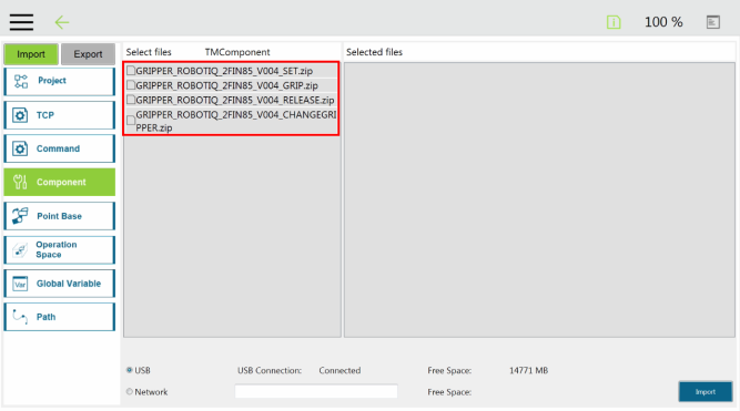
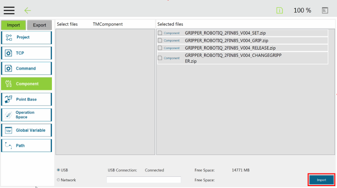
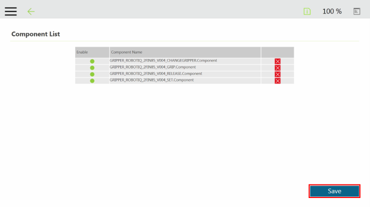
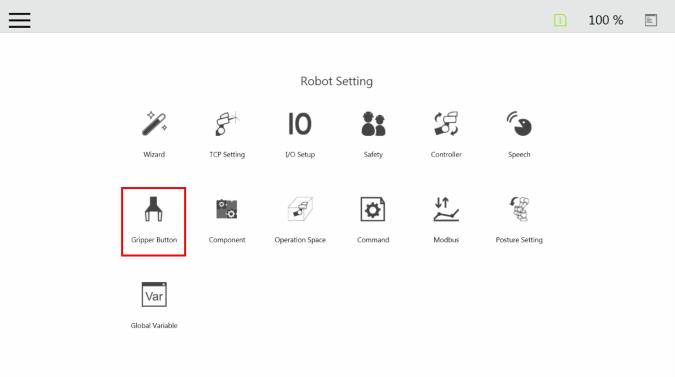
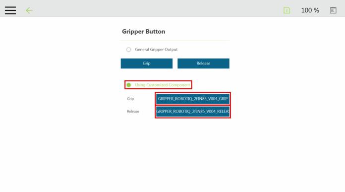
The user can assign Gripper Components to the Gripper button and use the latter to open and close the fingers of the Robotiq Gripper.

|
Component Icon |
Component Node |
|---|---|
|
|
|
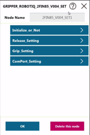
Fig. 4-9: SET Node Settings Menu
|
Setting |
Variable |
Type |
Default |
Description |
|
|---|---|---|---|---|---|
|
Initialize_or_Not |
var_reset |
bool |
false |
Set True if you want to initialize the gripper in this node. If you only want to chenge gripping force, position or speed, you don't need to initialize the gripper (please set false) |
|
|
Grip_Setting |
var_grip_force |
% |
50% |
Set gripping force |
|
|
2F-85 |
0~100%=20~235N |
||||
|
2F-140 |
0~100%=10~125N |
||||
|
var_grip_speed |
% |
50% |
Set gripping speed |
||
|
2F-85 |
0~100%=20~150mm/s |
||||
|
2F-140 |
0~100%=30~250mm/s |
||||
|
var_grip_pos |
% |
80% |
Set gripping position |
||
|
2F-85 |
0~100%=0~85mm/s |
||||
|
2F-140 |
0~100%=0~140mm/s |
||||
|
Release_Setting |
var_Release_force |
% |
50% |
Set gripping force |
|
|
2F-85 |
0~100%=20~235N |
||||
|
2F-140 |
0~100%=10~125N |
||||
|
var_Release_speed |
% |
50% |
Set gripping speed |
||
|
2F-85 |
0~100%=20~150mm/s |
||||
|
2F-140 |
0~100%=30~250mm/s |
||||
|
var_Release_pos |
% |
80 |
Set gripping position |
||
|
2F-85 |
0~100%=0~85mm/s |
||||
|
2F-140 |
0~100%=0~140mm/s |
||||
|
ComPort_Setting |
var_ComPort |
int |
1 |
Please set as Com1, Com2, Com3, following the com port to which you connect the gripper. |
|
|
Component Icon |
Component Node |
|---|---|
|
|
|
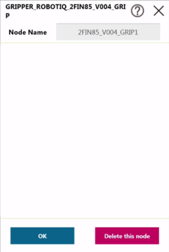
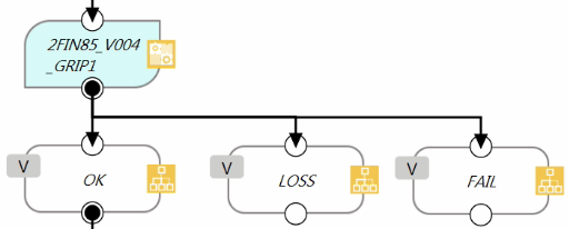
Fig. 4-10: GRIP Node Settings Menu
|
Setting |
Variable |
Type |
Default |
Description |
|
|---|---|---|---|---|---|
|
Grip_Setting (SET Node) |
var_grip_force |
% |
50% |
Set gripping force |
|
|
2F-85 |
0~100%=20~235N |
||||
|
2F-140 |
0~100%=10~125N |
||||
|
var_grip_speed |
% |
50% |
Set gripping speed |
||
|
2F-85 |
0~100%=20~150mm/s |
||||
|
2F-140 |
0~100%=30~250mm/s |
||||
|
var_grip_pos |
% |
80% |
Set gripping position |
||
|
2F-85 |
0~100%=0~85mm/s |
||||
|
2F-140 |
0~100%=0~140mm/s |
||||
|
Component Icon |
Component Node |
|---|---|
|
|
|
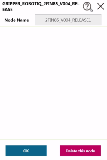
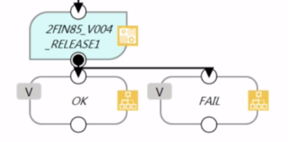
Fig. 4-11: RELEASE Node Settings Menu
|
Setting |
Variable |
Type |
Default |
Description |
|
|---|---|---|---|---|---|
|
Release_Setting (SET Node) |
var_grip_force |
% |
50% |
Set gripping force |
|
|
2F-85 |
0~100%=20~235N |
||||
|
2F-140 |
0~100%=10~125N |
||||
|
var_grip_speed |
% |
50% |
Set gripping speed |
||
|
2F-85 |
0~100%=20~150mm/s |
||||
|
2F-140 |
0~100%=30~250mm/s |
||||
|
var_grip_pos |
% |
80% |
Set gripping position |
||
|
2F-85 |
0~100%=0~85mm/s |
||||
|
2F-140 |
0~100%=0~140mm/s |
||||
|
Component Icon |
Component Node |
|---|---|
|
|
|
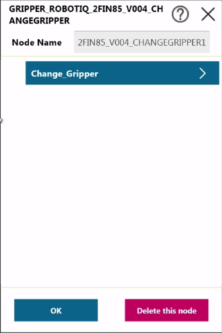
|
Setting |
Variable |
Type |
Default |
Description |
|
|---|---|---|---|---|---|
|
Change_Gripper |
Var_Slave_ID |
int |
9 |
Select the Slave ID as the current gripper |
|
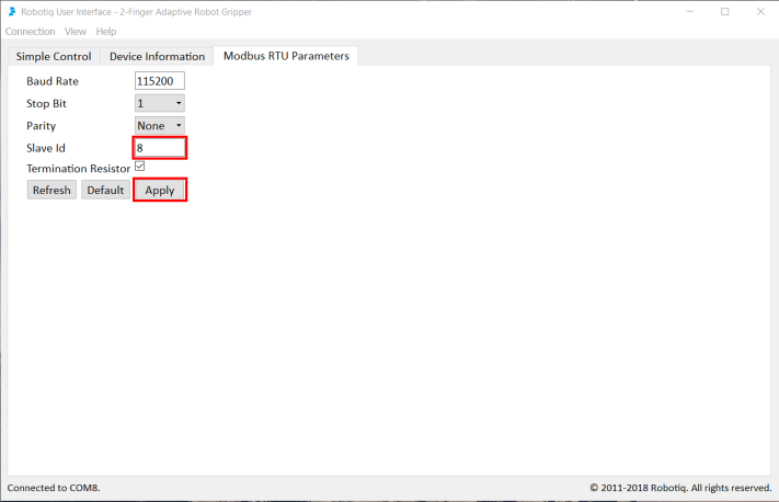
Info
Use the Robotiq User Interface to change the Modbus Slave ID Address of the second gripper when using a dual gripper (Default = 9).
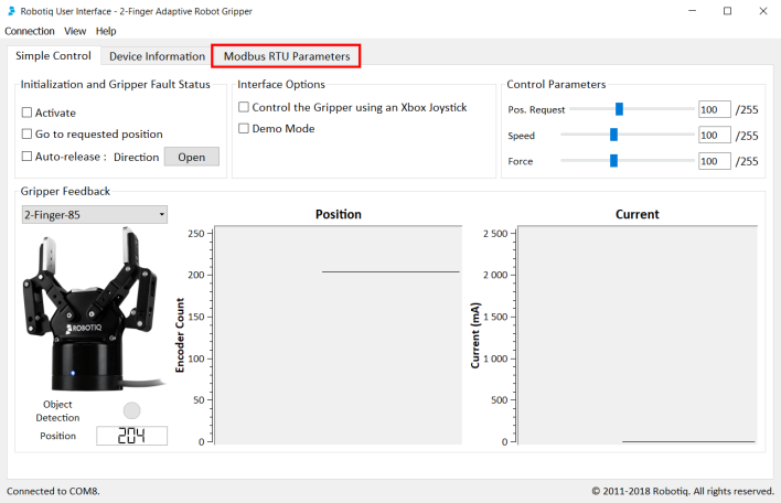
The user can change the Modbus Slave ID of a Robotiq Gripper via the Robotiq User Interface.
Installer
Browse to the support page of the Gripper in the Software section to download the RUI installer (.exe).
Robotiq User Interface
Browse to the support page of the Gripper, in the Documents section, to access or download the instruction manual of the Robotiq User Interface (RUI) for information on the installation and control of the RUI.