The following sub-sections provide instructions for the installation of the Force Copilot software package. This allows you to get data from a force torque sensor.
Force Copilot contains many features to program and control the robot’s arm using a sensor’s force and torque readings. The package provides:
The ActiveDrive Toolbar is automatically installed with the Force Copilot software Package. It enhances the guiding mode on Universal Robots by allowing the robot to be hand guided smoothly and easily towards a waypoint. The ActiveDrive feature is a great way to assist the Path recording described in the Path Recording section, by hand guiding the robot while recording a path.
Info
The Force Copilot software Package contains the ActiveDrive Toolbar. Therefore, the toolbar is automatically installed with the URCap Package.
Info
The ActiveDrive Toolbar can be installed and used without the URCap Package (refer to the UR Package without URCaps section for information on how to install the toolbar without the URCap).
Warning
Verify that the Force Torque Sensor is aligned with the robot arm using the dowel pin. This ensures that the Sensor’s axes are aligned with the robot and that the ActiveDrive feature will work correctly.
The robot speed set with the Speed slider will affect the speed at which the robot moves in the ActiveDrive mode. Verify and adjust the speed slider to the desired speed. It has to be greater than 50%.

Tap the ActiveDrive button to expand the toolbar.

(Tap the mode selector to expand.)
|
Primary icon |
Functionality name |
Description |
|---|---|---|
|
|
ActiveDrive |
Tap to toggle between the expanded and collapsed ActiveDrive Toolbar. When grey, the functionality is not available. Tap the button to see why it is not available. |
|
|
Start / Stop |
Tap to start or stop ActiveDrive. ActiveDrive will automatically turn off after 30s of inactivity. When started, ActiveDrive allows you to move the robot freely by applying forces on robot’s end-effector. This is different from the Free Drive feature on the robot, where you can move the robot arm. |
|
|
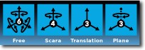
Modes |
Shows the current ActiveDrive mode. When tapping the icon, the available modes will appear and you can change to a different mode. ActiveDrive modes allow you to restrain the robot to specific movements. |
|
|
Free |
Free motion: all translations and rotations are allowed. |
|
|
Scara |
SCARA-style motion: all translations and horizontal rotation (twist) are allowed. |
|
|
Translation |
Translation motion: only translations are allowed. No rotation of the robot is possible in this mode. |
|
|
Plane |
Plane motion: horizontal translations and horizontal rotations (twist) are allowed (no vertical motions are allowed). |
|
|
Drift Control |
Tap this button to stop the robot from drifting (resets the sensor’s offset). |
|
|
Speed |
Motion speed control is toggled between fast and slow, allowing precise movement in slow motion. The force torque sensor will switch to slow speed automatically whenever high forces are detected, for example, during an impact with an object. |
|
|
Square robot |
Aligns the tool center point (TCP) orientation with the robot base. Tap and hold this button to automatically move the end-effector to the closest orthogonal orientation of the base axis system (just try it, you will see!). |
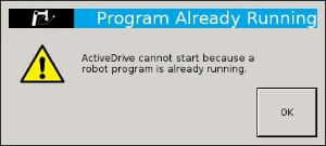
The ActiveDrive Toolbar will be automatically collapsed and be grayed whenever one of the following situations occurs. In such cases, by tapping the ActiveDrive button, the following messages will appear:
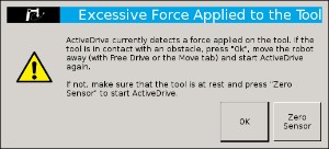
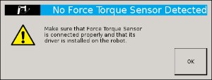
Force Torque Sensor is detected: Check the Force Torque Sensor’s connection. Make sure the USB adapter and all the wires are connected. Also, verify the Sensor’s LED status (refer to the Status LED section).
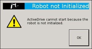
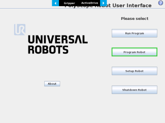
The robot is not initialized: Tap OK and go to PolyScope’s home page. Tap Setup Robot and go to Initialize Robot to start the robot.


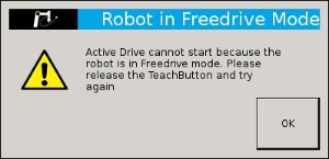
If the Freedrive button is pressed: The ActiveDrive mode cannot be used when the Free Drive mode is ON. Make sure you are not pressing on the teach pendant’s Teach button when trying to use the ActiveDrive toolbar.
Force Torque Sensor functions are made available in the Universal Robots functions drop-down menu.

Fig. 4.1: Example of two reference frames for the express_force_in_frame(<T_from_to>,<wrench_from>) function
Info
Although displayed in real time in the Variables tab, the force and torque values can be seen in the Force Copilot Dashboard.
After the calibration has been completed, go to the FT 300 Dashboard to monitor the force and torque values in real time.
Prior to using the FT Sensor's data in the framework of a robot program, it is recommended to zero the sensor using the Zero sensor button.
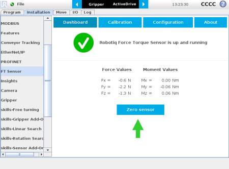
Fig. 4.2: Force Copilot Dashboard with force and torque values displayed in real time.
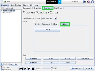
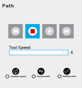
The Force Copilot software package adds a Path feature in PolyScope which can be used to record paths directly by moving the robot. The ActiveDrive Toolbar is a great tool to use while recording a path, as it is an easy way to hand guide the robot’s end-effector. Path recording can be used for specific processes requiring complex paths (polishing, gluing, etc.) or more generally for any useful case that would require programming a high number of waypoints. The Path node offers options to modify the recorded path to change its speed and play the path backwards or relative to a variable start position.
How to add and record a path
|
|
|
|
|
|
|
|
Path recording and visualization. |
|
|
Path speed box. |
|
|
Path options. |
|
|
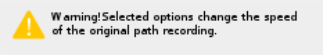
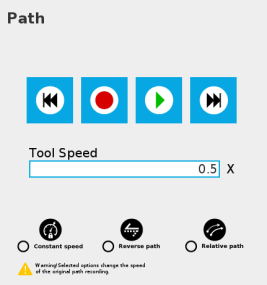
Warning section. Displayed whenever a setting results in a duration different than the original path duration. |
|
|
When a Path node is empty (no path recorded), the only available button is the record button. |
|
|
While recording a path, the only available button is the stop button. |
|
|
When the speed of the original recording is modified using the speed slider, a warning message appears and the path time and speed information is updated. |
|
Primary icon |
Description |
|---|---|
|
|
Starts and stops the path recording. |
|
|
Press and hold in order to move the robot at the path’s start. |
|
|
Press and hold in order to move the robot at the path’s end. |
|
|
Press and hold in order to move the robot to the path’s start and play the path as it will be executed in the program. |
|
|
If selected, the path is modified to play at a constant tool speed (linear speed at the tool center point). With this option, all pauses and hesitations (dead times) in the path will be removed. |
|
|
If selected, the recorded path will be played backwards in the program. It can be useful if a path is copied and played backwards, resulting in a path played back and forth. |
|
|
If selected, the path will be played relative to the current robot position when the program enters the path instruction. This effectively offsets all the recorded path. |
|
|
Displayed whenever a setting results in a duration different than the original path duration. |
* When an icon is greyed, it means it is unavailable.
If you tap the record button when a path is already recorded in a node, a warning pop-up will ask if you want to overwrite the path (tap OK) or keep the previously recorded path (tap Cancel).
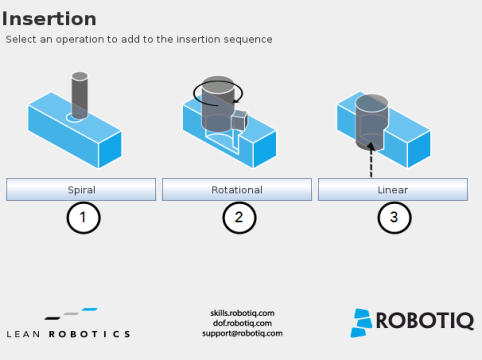
The Force Copilot software Package includes Insertion nodes, which can be used to perform spiral, rotational and linear movements to insert objects in holes or bores, or to make contact with a surface. It is an essential integration resource for streamlining robot programs in the framework of precise assembly applications.
When the task is performed by a human operator, the operator's fingers provide valuable feedback through the sense of touch, thus allowing the human to detect any resistance when trying to insert a pin in a hole, for instance. To a certain extent, Force Copilot gives that kind of sensitivity to the end effector.
How to add an Insertion node
Info
The parent Insertion node is automatically followed by a Zero Sensor child node.
|
Spiral
|
Rotational Following a contact established between the object grasped by the end effector (or the effector itself) and the corresponding mating part or surface, a rotational motion is engaged on a specific plane to find the path of least resistance, according to the direction, speed, force, maximum torque and maximum rotation angle parameters set by the user.
|
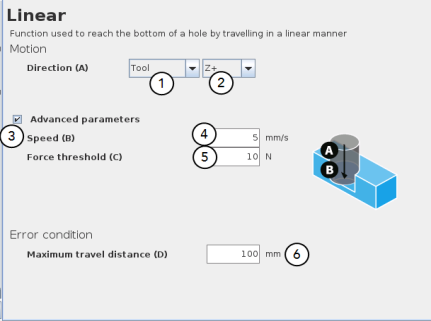
Linear Following the successful spiral, rotational or fortuitous location of a mating hole or bore, a linear motion is engaged at a certain speed until the force threshold or maximum travel distance is reached. |
The Spiral child node is packaged with an On error condition line to be populated with a program instruction when/if the error condition occurs. The potential sequence after the Spiral instruction is followed by a program halt, by default.
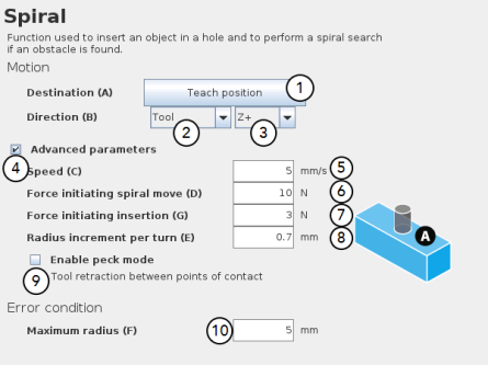
Default values and units of measurement
|
Parameter |
Unit of measurement |
Default value |
|---|---|---|
|
Reference frame (Direction) |
N/A |
Tool |
|
Axis (Direction) |
N/A |
Z+ |
|
Speed |
mm/s |
5 |
|
Force initiating spiral move |
N |
10 |
|
Force initiating insertion |
N |
3 |
|
Radius increment per turn |
mm |
0.7 |
|
Maximum radius (Error condition) |
mm |
5 |
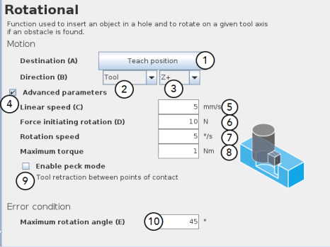
Default values and units of measurement
|
Parameter |
Unit of measurement |
Default value |
|---|---|---|
|
Reference frame (Direction) |
N/A |
Tool |
|
Axis (Direction) |
N/A |
Z+ |
|
Linear speed |
mm/s |
5 |
|
Force initiating rotation |
N |
10 |
|
Rotation speed |
°/s |
5 |
|
Maximum torque |
Nm |
1 |
|
Maximum rotation angle (Error condition) |
° |
45 |
|
Parameter |
Unit of measurement |
Default value |
|---|---|---|
|
Reference frame (Direction) |
N/A |
Tool |
|
Axis (Direction) |
N/A |
Z+ |
|
Speed |
mm/s |
5 |
|
Force threshold |
N |
10 |
|
Maximum travel distance (Error condition) |
mm |
100 |
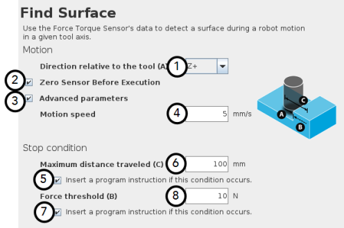
The Force Copilot software package includes the Find Surface node, which is a great tool for machine tending and various other applications that require repeated accurate positioning of objects.
The default parameters of the function allow for a versatile demo or a quick test of the features while the advanced parameters make it a more customizable asset.
How to add a Find Surface node
|
Parameter |
Unit of measurement |
Default value |
|---|---|---|
|
Direction relative to the tool |
N/A |
Z+ |
|
Motion speed |
mm/s |
5 |
|
Maximum distance traveled (Stop condition) |
mm |
100 |
|
Force threshold (Stop condition) |
N |
10 |
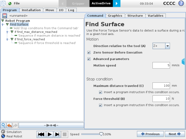
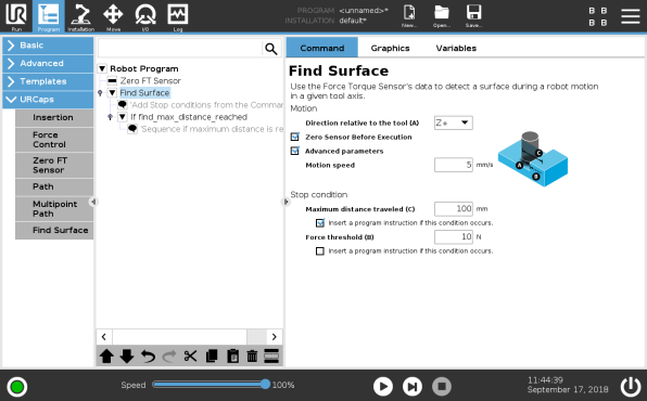
Fig. 4.3: Find Surface node with stop condition(s)
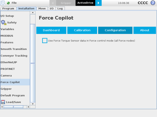
In order to use the FT Sensor's data in Force control mode for all Force nodes, go to the Configuration tab and check the corresponding box. This will feed the Sensor's force values to the UR Force mode as an alternative to UR's embedded force feedback.
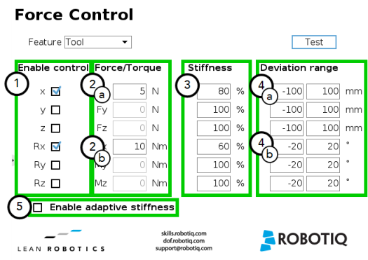
The Robotiq Force Control node is used to apply force and torque values along and around axes.
How to add a Force Control node
Warning
UR Move nodes (MoveL, MoveJ, MoveP) and Force nodes cannot be executed as child of the Robotiq Force Control node.
Tip
Where a UR Move node would normally be used, the user shall record a Robotiq Path emulating the desired Move.
In a situation where the user wants to make contact with a surface in accordance with the user-defined settings, a Wait instruction can be inserted as child of the Robotiq Force Control.
The Force Control node is primarily meant to be used with a Robotiq Path node.
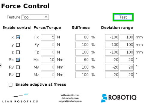
With the various user-defined settings available, operators can use a force torque sensor to apply force/torque and thus follow irregular shapes and/or surfaces for applications such as polishing, deburring, finishing, dispensing, etc.
The user can select a reference frame from a dropdown menu, as shown below.
The Tool reference frame uses the X, Y and Z axes of the end-effector to apply force and torque values in the appropriate direction.
On the other hand, the Base reference frame takes into consideration the X, Y and Z axes of the robot arm base.
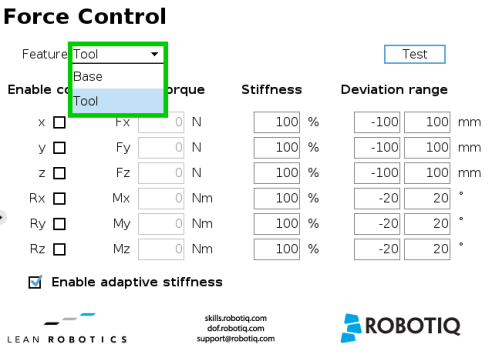
Fig. 4.4: Force Control node with Reference Feature dropdown highlighted.
Info
Tapping the text boxes brings up a numpad used to enter the values.
Example
In a situation where 10 N are applied exclusively along the Z-axis, with 20% stiffness along the X and Y axes, and a deviation range that goes from -50 mm to +50 mm along all axes...

|

|
Fig. 4.5: Deviation range - On the left, no deviation range has been entered. On the right, a deviation range of at least 15 degrees has been entered around the corresponding axis.
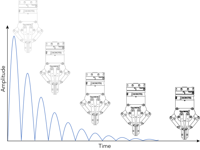
Fig. 4.6: End-effector experiencing adaptive stiffness upon repeated contact with a surface
The Test button applies the user-defined settings of the Force Control node to the sensor, therefore moving along/around the corresponding axes, if the control had been enabled for the latter, regardless of other instructions entered before or after the Force Control node in the program tree.
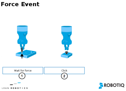
The Force Copilot software package includes Force Event, which can be used to perform a click detection or to wait for a specific force or torque.
How to add a Force Event function
|
Wait for Force The Wait for force feature is used to detect a specific force or torque inside a Force Control node. |
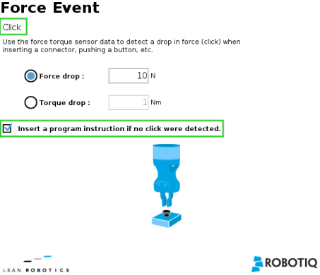
Click Detection The Click Detection feature is used to detect a drop that is followed by a rise of a force or a torque. |
The Click Detection feature monitors forces and torques throughout the nodes placed within it. This feature senses if a drop in the force or torque is then followed by a sudden rise, thus making a "click". If a click is detected within the Click detection node, the program then skips the remaining instruction lines that are included in the Click detection node. The program automatically goes to the following instruction.
Indeed, a program instruction can be added if no click is detected.
Tip
To perform a click button action, as shown by the animated gif, a Find Surface function has to be added up in the Click detection node.
The Wait for Force feature is used to detect a specific force or torque inside a Force Control node. The program waits until the force or torque is reached prior to the program continuation. The values are defined by the Force Control's force and torque parameters. To be sure the program is not incessantly running, a Timeout option is available.

The Collision Detection feature is used to stop a program when the forces and the torques, monitored
How to add a Collision Detection
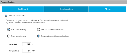
You can either choose to halt (stop) or suspend (pause) the program when a collision is detected. The forces and torques monitored in the collision detection node are the ones measured by the
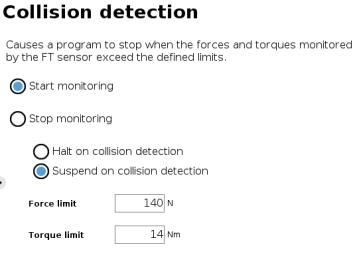
.
The Collision Detection feature in the installation tab can be configured to start the monitoring upon every robot program start. On the other hand, the Collision Detection node in the Program tab starts a thread that runs in parallel with the rest of the robot program. If the Stop monitoring option is selected in the Collision Detection node, the thread stops and the program continues without monitoring the force or the torque.
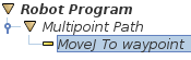
The Multipoint Path node is an advanced version of the Path node, combining complex trajectory recording and point-to-point teaching, with the option to define each segment as a straight line or as a curve.
Tip
Try inserting a Multipoint Path node in a Robotiq Force Control node. The former will perform the movements that were taught while taking into consideration the parameters set in the latter.
How to add a Multipoint Path node
![]()
Fig. 4.7: Multipoint Path node (empty)
Info
Please note that a Multipoint Path parent node is always followed by a MoveJ command leading to the starting waypoint of the path sequence.
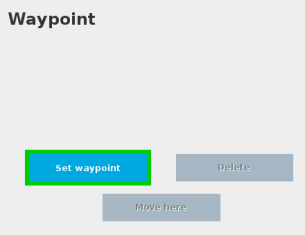
At this point, the interface will look like this:
Important
Whether the path is made of straight lines, curves or a mix of both, it inevitably passes through each waypoint set by the user.
Important
The curve segments are not generated and/or represented according to a spline model; they are rather based on Bézier curves.
Info
For describing the continuity of the curves used in the Multipoint Path node, control points are generated on the bisector of each waypoint junction (angle). Curves are therefore tangent to those bisectors.
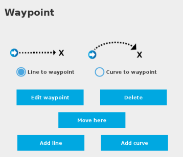
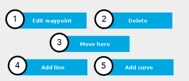
Fig. 4.8: Multipoint Path interface with Line/Curve options.
Caution
Adding several waypoints (lines or curves) without moving the robot in between them will result in the generation of identical waypoints.
In order to remedy this situation, the user can edit each waypoint created and adjust its position.
Tip
You can toggle at any time between the Line to waypoint and Curve to waypoint options.
Select the waypoint in the program tree and tap the appropriate radio button in the Command tab.
Repeat step 2 until you complete your Multipoint Path.
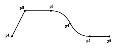
Fig. 4.9: Representation of a six-waypoint Multipoint Path with both curves and straight lines.
The Robotiq Force Torque Sensor development package can be downloaded at support.robotiq.com.
The development package is distributed under the New BSD license, which is a permissive free software license. In short, the provided code can be used in any project without any restriction regarding its use (commercial or not). If it is included in a software, this software does not need to be open-source. However, the code is provided "as is" without any liability from Robotiq and some restrictions apply regarding the distribution of the code and the use of the Robotiq name.
The terms of the license (included in each source file) are described here:
Software License Agreement (BSD License) Copyright (c) 2014, Robotiq, Inc. All rights reserved. Redistribution and use in source and binary forms, with or without modification, are permitted provided that the following conditions are met: - Redistributions of source code must retain the above copyright notice, this list of conditions and the following disclaimer. - Redistributions in binary form must reproduce the above copyright notice, this list of conditions and the following disclaimer in the documentation and/or other materials provided with the distribution. - Neither the name of Robotiq, Inc. nor the names of its contributors may be used to endorse or promote products derived from this software without specific prior written permission. THIS SOFTWARE IS PROVIDED BY THE COPYRIGHT HOLDERS AND CONTRIBUTORS "AS IS" AND ANY EXPRESS OR IMPLIED WARRANTIES, INCLUDING, BUT NOT LIMITED TO, THE IMPLIED WARRANTIES OF MERCHANTABILITY AND FITNESS FOR A PARTICULAR PURPOSE ARE DISCLAIMED. IN NO EVENT SHALL THE COPYRIGHT OWNER OR CONTRIBUTORS BE LIABLE FOR ANY DIRECT, INDIRECT, INCIDENTAL, SPECIAL, EXEMPLARY, OR CONSEQUENTIAL DAMAGES (INCLUDING, BUT NOT LIMITED TO, PROCUREMENT OF SUBSTITUTE GOODS OR SERVICES; LOSS OF USE, DATA, OR PROFITS; OR BUSINESS INTERRUPTION) HOWEVER CAUSED AND ON ANY THEORY OF LIABILITY, WHETHER IN CONTRACT, STRICT LIABILITY, OR TORT (INCLUDING NEGLIGENCE OR OTHERWISE) ARISING IN ANY WAY OUT OF THE USE OF THIS SOFTWARE, EVEN IF ADVISED OF THE POSSIBILITY OF SUCH DAMAGE. |
The development package is structured with the following files and directories architecture (non-Linux files and directories are ignored in this section):
Caution
When started, the provided software will scan all ports in the system (ttySx and ttyUSBx) to find a compatible Robotiq device. It uses the Linux utility "fuser" to determine if the port is already opened. This section of code can be modified by the user if necessary to avoid the scanning of ports (for example, if another device would become confused when receiving a message that it cannot understand).
This procedure explains how to compile the source code and verify that the sensor data is properly read.
rd@debian:~/$ cd driver
rd@debian:~/$ make linux
rd@debian:~/$ sudo usermod -a -G dialout username
rd@debian:~/$ ls -l /dev | grep ttyUSB
rd@debian:~/driver/Linux/bin/$ ./driverSensor
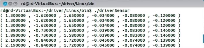
Fig. 4.10: Sensor Data Acquisition.
In practice, the provided source code will be adapted to either: be incorporated with a custom application or to communicate with one. At this point, the main.c file should be adapted according to the guideline comments inserted in the code.
Caution
Please note that Robotiq can only support our customers in making sure they can compile and test the provided code as is.
No support can be provided for the integration of the provided source code into a custom application.
The development package is structured with the following files and directories architecture (non-Windows files and directories are ignored in this section):
This procedure explains how to install MinGW, compile the provided source code and verify that the sensor data is properly read.
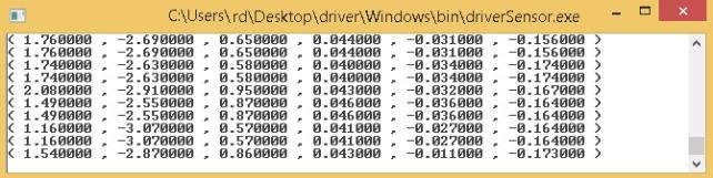
Fig. 4.11: Sensor Data Acquisition Under Windows.
In practice, the provided source code will be adapted to either: be incorporated with a custom application or to communicate with one. At this point, the main.c file should be adapted according to the suggested comments inserted in the code.
Caution
Please note that Robotiq can only support our customers in making sure they can compile and test the provided code as is.
No support can be provided for the integration of the provided source code into a custom application.
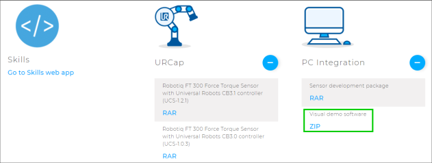
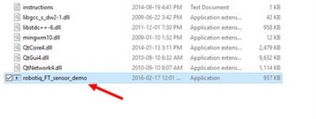
The Visual Demo Software is used to demonstrate the ability of the FT Sensor to read force and moment. It is not intended to be used for programming or to save or use data. It can also be used to calibrate the Sensor. Please refer to the Calibration Procedure for the Visual Demo Software (PC) section for the calibration procedure.
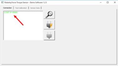
By going into the Sensor Data tab, you can now see in real time the force and moment applied on the FT Sensor.
The FT Sensor uses two communication modes, Modbus RTU and data stream. The Modbus RTU communication mode is used to obtain information on the Sensor, like its firmware version. The data stream mode is used to obtain data from the Sensor.
Info
It is recommended to use the FT Sensor data stream to obtain faster data acquisition.
Caution
Modbus RTU can be used to obtain data, but will result in a slower data acquisition frequency.
Info
In both modes, force and torque data from the Sensor will be in 16-bits signed integer format.
The FT Sensor can be controlled over USB using an ACC-ADT-USB-RS485 signal converter. This section is intended to provide guidelines for setting up a Modbus scanner that will adequately communicate with the Sensor.
For a general introduction to Modbus RTU and for details regarding the CRC algorithm, the reader is invited to read the Modbus over serial line specification and implementation guide available at: : http://www.modbus.org/docs/Modbus_over_serial_line_V1_02.pdf.
For debugging purposes, the reader is also invited to download one of many free Modbus scanners such as the CAS Modbus Scanner from Chipkin Automation Systems available at: http://www.store.chipkin.com/products/tools/cas-modbus-scanner.
Info
Modbus RTU is a communication protocol based on Big Endian byte order. Therefore, the 16-bit register addresses are transmitted with the most significant byte first. However, the data port is, in the case of Robotiq products, based on the Little Endian byte order. As such, the data parts of Modbus RTU messages are sent with the less significant byte first.
Tip
Modbus RTU specification and details can be found at www.modbus.org
The following table describes the connection requirements for controlling the Sensor using the Modbus RTU protocol:
|
Propriety |
Value |
|---|---|
|
Baudrate (bps) |
19,200 |
|
Data bits |
8 |
|
Stop bit |
1 |
|
Parity |
None |
|
Supported Functions |
Read Holding Register (FC03) Preset Multiple Register (FC16) |
|
Slave ID |
0x0009 (9) |
In Modbus RTU you can obtain the following information:
|
Information |
Register |
|---|---|
|
Production year- |
514 |
|
Serial number |
510 to 513 |
|
Force X (N) = value / 100 |
180 |
|
Force Y (N) = value / 100 |
181 |
|
Force Z (N) = value / 100 |
182 |
|
Moment X (Nm) = value / 1000 |
183 |
|
Moment Y(Nm) = value / 1000 |
184 |
|
Moment Z (Nm) = value / 1000 |
185 |
|
Acceleration X (g) = value / 1000 |
190 |
|
Acceleration Y (g) = value / 1000 |
191 |
|
Acceleration Z (g) = value / 1000 |
192 |
Function code 03 (FC03) is used to read the status of the Sensor (robot input). Examples of such data is the display of the current force and torque values.
Example of FC03 Read Function:
To get Fx, you need to read (03) the register 180 (00B4) in device ID 9 (09).
Request is: 09 03 00 B4 00 01 C5 64
Hex format: 0x09 0x03 0x00 0xB4 0x00 0x01 0xC5 0x64
|
Bits |
Description |
|---|---|
|
09 |
SlaveID |
|
03 |
Function Code 03 (Read Holding Register) |
|
00B4 |
Address of the first requested register |
|
0001 |
Number of registers requested (1) |
|
C564 |
Cycle Redundancy Check (CRC) |
To get all 6 force/torque values at once, you need to read (03) six registers (0006), starting with register 180 (00B4) in device ID 9 (09).
Request is: 09 03 00 B4 00 06 04 A6
Hex format: 0x09 0x03 0x00 0xB4 0x00 0x06 0x84 0xA6
|
Bits |
Description |
|---|---|
|
09 |
SlaveID |
|
03 |
Function Code 03 (Read Holding Register) |
|
00B4 |
Address of the first requested register |
|
0006 |
Number of registers requested (6) |
|
04A6 |
Cycle Redundancy Check (CRC) |
Data stream mode is the recommended method of obtaining data from the Sensor. Once initiated, the Sensor will stream force and moment data continuously until communication is interrupted by the user.
Tip
To start the data stream, write 0x0200 in register 410.
For a setup over Universal Robots, Data stream will be accessible on TCP port 63351 of your machine.
Tip
With a Universal Robot, you can access the data stream using the documentation available at UR : Remote Control Via TCP/IP - 16496
To stop the data stream, communication must be interrupted by sending a series of 0xff characters to the Sensor. Sending for about 0.5s (50 times) will ensure that the Sensor stops the stream.
When the stream is started, 16 bytes messages are sent by the sensor at 100Hz using this format:
<0x20><0x4e><LSB_data1><MSB_data1> ... <LSB_data6><MSB_data6><LSB_crc><MSB_crc>
With dataX being a 16-bits signed integer defined as:
|
Data |
Value meaning |
|---|---|
|
data1 |
Fx * 100 (N) |
|
data2 |
Fy * 100 (N) |
|
data3 |
Fz * 100 (N) |
|
data4 |
Mx * 1000 (Nm) |
|
data5 |
My * 1000 (Nm) |
|
data6 |
Mz * 1000 (Nm) |
The CRC is computed using a standard 16-bits modbus CRC (see http://www.ccontrolsys.com/w/How_to_Compute_the_Modbus_RTU_Message_CRC).
Function code 16 (FC16) is used to activate functionalities of the Gripper (robot output). A common example is the initialization of data streaming.
Example of setting multiple registers (FC16):
To initialize the data stream, 0x0200 must be written with the function 16 (0x10) in register 410 (019A).
Request is: 09 10 01 9A 00 01 02 02 00 CD CA
Hex format: 0x09 0x10 0x01 0x9A 0x00 0x01 0x02 0x02 0x00 0xCD 0xCA
|
Bits |
Description |
|---|---|
|
09 |
SlaveID |
|
10 |
Function Code 16 (Preset Multiple Registers) |
|
019A |
Address of the first register |
|
0001 |
Number of registers requested (1) |
|
02 |
Number of data bytes to follow (1 registers x 2 bytes/register = 2 bytes) |
|
0200 |
Value written to register 0x019A |
|
CDCA |
Cycle Redundancy Check (CRC) |