
The following subsections will guide you through the installation and general setup of your Robotiq Hand-E Gripper.
Warning
Before installing:
Warning
When installing:
Standard upon delivery
Info
Please refer to the Spare Parts, Kits and Accessories section for a list of available couplings.
Caution
The following are not included in the standard delivery:
Info
When bought as a kit, the Hand-E Gripper will come in a package with the appropriate coupling, fingers/fingertips and cabling. Please refer to the Spare Parts, Kits and Accessories section.
The following tools are required to install the Hand-E Gripper:
Optional tools if installing fingertip/holder kits: HND-FIN-ALU-KIT, HND-TIP-RUB-KIT, HND-TIP-VGR-KIT, HND-TIP-HLD-KIT
The following parts are required for setup :
The Gripper needs to be supplied by a DC voltage source. This power supply is not included with the Gripper. Required power supply must match the Robotiq device. The following table shows the specifications with regards to the power supply required to operate the Gripper and the optional Robotiq Controller.
Table 3-1: Hand-E power supply requirements.
1 Suggested fuse is a: Phoenix Contact # 0916605 2 A thermal, use AWG #20 wiring.
Warning
If your power supply could exceed the specified regulation, over-voltage protection is required.
Robotiq recommends the use of the following power supplies:
Tip
Optional Robotiq Universal Controller can use the same power supply.
|
CONDITION |
VALUE |
|---|---|
|
Minimum storage/transit temperature |
-30°C [-22°F] |
|
Maximum storage/transit temperature |
60°C [140°F] |
|
Minimum operating temperature |
-10°C [14°F] |
|
Maximum operating temperature |
50°C [122°F] |
|
Humidity (non-condensing) |
20-80% RH |
|
Vibration |
< 0.5G |
|
Other |
IP 67 |
Table 3-2: Environmental and operating conditions of the Hand-E Gripper.
The figures below list the material and tools needed to mount fingers or fingertips/holders onto the racks of the Hand-E Gripper.
Fig. 3-1: Mounting the fingers on the racks

Fig. 3-2: Mounting fingertips on holders (and then on the racks)
Here are the steps to follow to mount the Gripper to your robot (see figure below). Note that all screws must be locked in place using medium strength threadlocker.
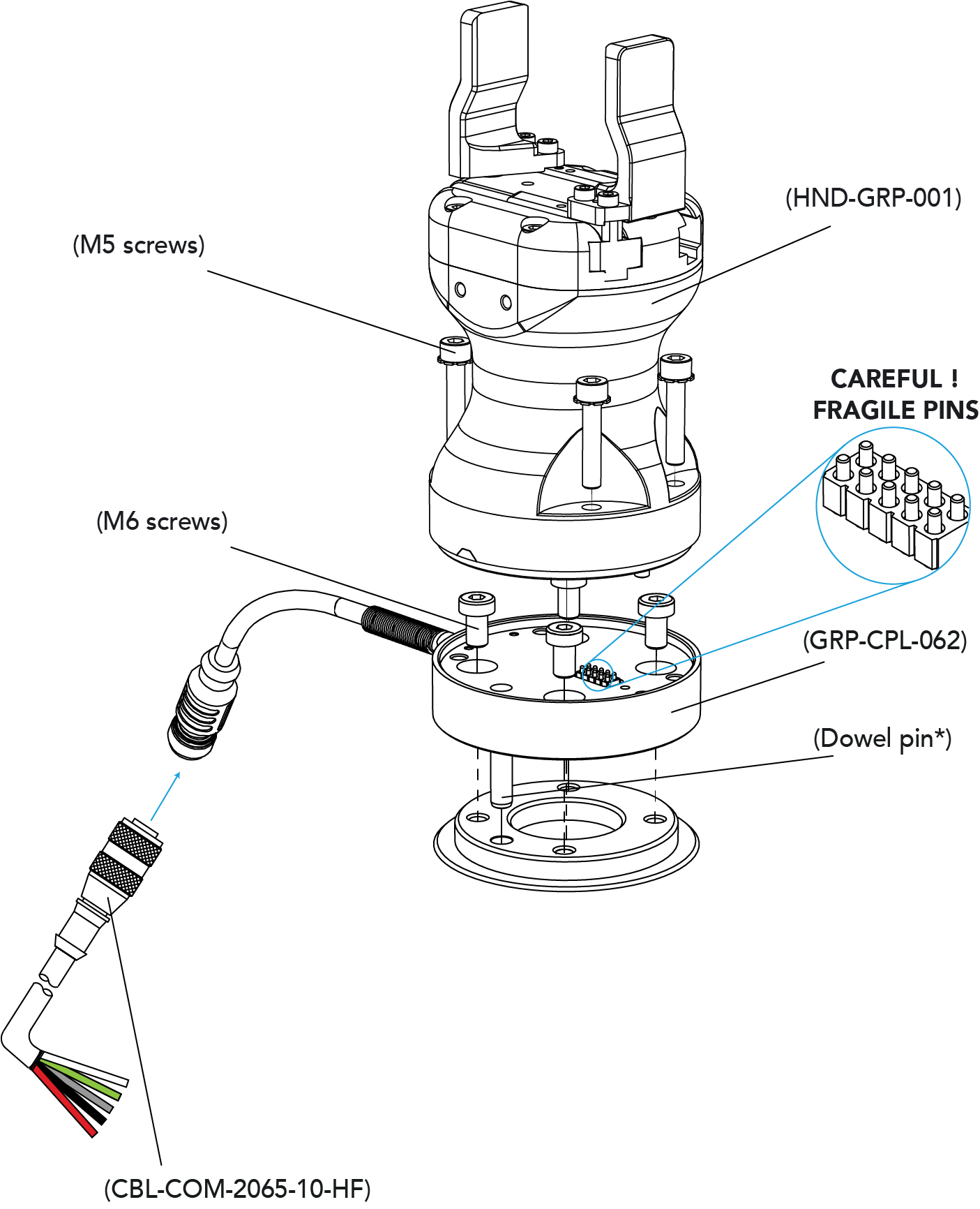
Fig. 3-3: Installing the Gripper onto the robot wrist
When installing multiple grippers on one robot, every gripper must have its own coupling.

Fig. 3-4: Dual Hand-E Gripper Configuration
Power and communication are established with the Hand-E Gripper via a single device cable. The device cable provides a 24V power supply to the Gripper and enables serial RS485 communication to the robot controller.
Info
RS485 signals (485+, 485- and 485 GND) are isolated from the main 24V power supply. GND can be connected to any other ground reference as long as the voltage potential between the grounds does not exceed 250V. Grounding reference is at the user's discretion.
The Gripper interfaces with its coupling via a 10-spring pin connector located on its outer surface.

Info
The coupling used in the figure above is used for reference only and corresponds to bolt pattern ISO 9409-1-50-4-M6.
An optional Robotiq Universal Controller may be used between the Gripper and the network/robot controller if fieldbus communication is required.
If a Robotiq Universal Controller is used, please refer to the instruction manual of the Robotiq Universal Controller. The figure below represents the wiring scheme of the Hand-E Gripper with device cable, power supply, fuse (refer to the Required Tools and Equipment section) and grounding.
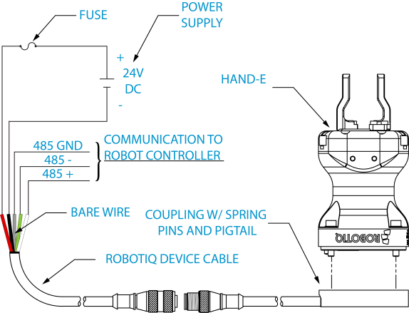
Fig. 3-5: Robotiq Hand-E with pigtail cable and device cable wiring scheme.
Caution
Use proper cabling management. Make sure to leave enough slack in the cabling to allow movement of the Gripper along all axes without pulling out the connectors. Always protect the controller side (robot side) connector of the cable with a strain relief cable clamp.
The figure below illustrates the Hand-E Gripper pigtail connector from the coupling (GRP-CPL-062 or AGC‑CPL‑XXX-002), the device cable on the robot side (CBL‑COM‑2065‑10-HF) and their associated pinout.
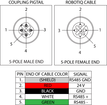
Table 3-3: Pinout of the Hand-E Gripper pigtail and device cable.
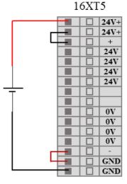
Fig. 3-6: Finger Adaptive Robot Gripper wiring to robot controller.
It is possible to connect and control up to four grippers on the same UR robot. Only one USB to RS485 converter (ACC- ADT-USB-RS485) must be used. Use M12 splitters (ACC-SPLIT-M12-2:1) to connect all the grippers pigtails to one 10m cable
(CBL-COM-2065-10-HF) that connects to the RS485 to RS232 converter.
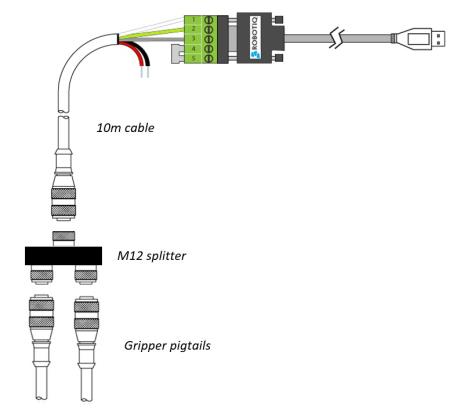
Fig. 3-7: Multiple grippers wiring.
Once installed and properly secured, your Robotiq Hand-E Gripper should be tested with the Robotiq User Interface test software using the provided USB converter. To do so :
Use the provided RS-485 to USB converter ACC-ADT-USB-RS485 (refer to the figure below) to plug into a PC with the Robotiq User Interface installed.
Caution
The Activate command will initiate movement of the Gripper for the auto-calibration procedure. Do not interfere with the Gripper. Be sure you have met robot safety measures.
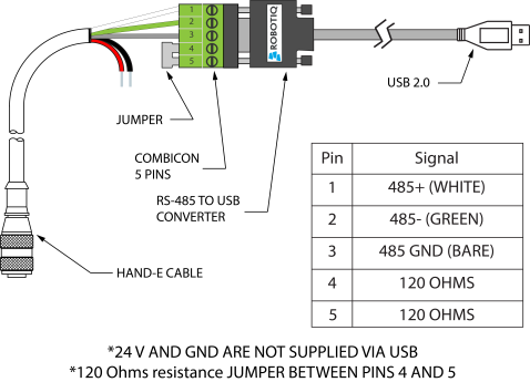
Fig. 3-8: RS-485 to USB converter ACC-ADT-USB-RS485 pinout.
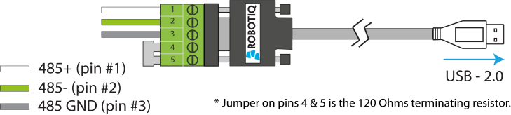
Fig. 3-9: Wiring possibilities of the USB to RS-485 converter.
Tip
With the RUI controlling the Gripper, you can go to the "view" menu to see input and output register values to further your understanding on how to command the Gripper. You can also test gripping your parts with various speed and force settings. Please refer to the Control section for details.
Here are the steps to follow to install the Gripper on the robot.