
The following subsections will guide you through the installation and general setup of your Robotiq Hand-E Gripper.
Warning
Before installing:
Warning
When installing:
Standard upon delivery
Info
When bought as a kit, the Hand-E Gripper will come in a package with the appropriate coupling, fingers/fingertips and cabling. Please refer to the Spare Parts, Kits and Accessories section.
The following tools are required to install the Hand-E Gripper:
Optional tools if installing fingertip/holder kits: HND-FIN-ALU-KIT, HND-TIP-RUB-KIT, HND-TIP-VGR-KIT, HND-TIP-HLD-KIT
|
CONDITION |
VALUE |
|---|---|
|
Minimum storage/transit temperature |
-30°C [-22°F] |
|
Maximum storage/transit temperature |
60°C [140°F] |
|
Minimum operating temperature |
-10°C [14°F] |
|
Maximum operating temperature |
50°C [122°F] |
|
Humidity (non-condensing) |
20-80% RH |
|
Vibration |
< 0.5G |
|
Other |
IP 67 |
Table 3-1: Environmental and operating conditions of the Hand-E Gripper.
The figures below list the material and tools needed to mount fingers or fingertips/holders onto the racks of the Hand-E Gripper.
Fig. 3-1: Mounting the fingers on the racks

Fig. 3-2: Mounting fingertips on holders (and then on the racks)
You must use a coupling to attach the Gripper to the robot.
Here are the steps to follow to mount the Gripper on the robot (exploded view in the figure below). Note that all screws should be locked using medium strength threadlocker.
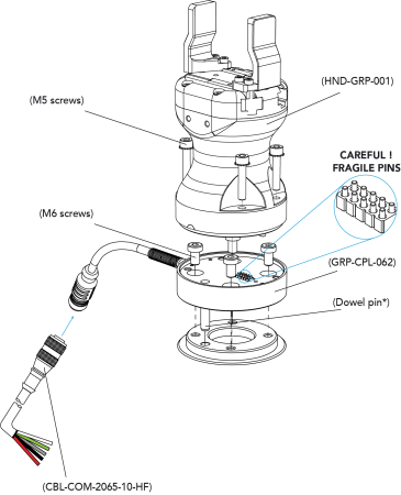
Fig. 3-3: Installing the Gripper onto the robot wrist
When installing multiple grippers on one robot, every gripper must have its own coupling.

Fig. 3-4: Dual Hand-E Gripper Configuration
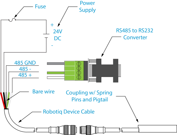
Power and communication are established with the Hand-E Gripper via a single device cable. The device cable provides a 24V power supply to the Gripper and enables serial RS485 communication to the robot controller.
Info
RS485 signals (485+, 485- and 485 GND) are isolated from the main 24V power supply. GND can be connected to any other ground reference as long as the voltage potential between the grounds does not exceed 250V. Grounding reference is at the user's discretion.
The Gripper interfaces with its coupling via a 10-spring pin connector located on its outer surface.

Info
The coupling used in the figure above is used for reference only and corresponds to bolt pattern ISO 9409-1-50-4-M6.
An optional Robotiq Universal Controller may be used between the Gripper and the network/robot controller if fieldbus communication is required.
If a Robotiq Universal Controller is used, please refer to the instruction manual of the Robotiq Universal Controller. The figure below represents the wiring scheme of the Hand-E Gripper with device cable, power supply, fuse (refer to the Required Tools and Equipment section) and grounding.
Caution
Use proper cabling management. Make sure to leave enough slack in the cabling to allow movement of the Gripper along all axes without pulling out the connectors. Always protect the controller side (robot side) connector of the cable with a strain relief cable clamp.
The figure below illustrates the Hand-E Gripper pigtail connector from the coupling (GRP-CPL-062 or AGC‑CPL‑XXX-002), the device cable on the robot side (CBL‑COM‑2065‑10-HF) and their associated pinout.
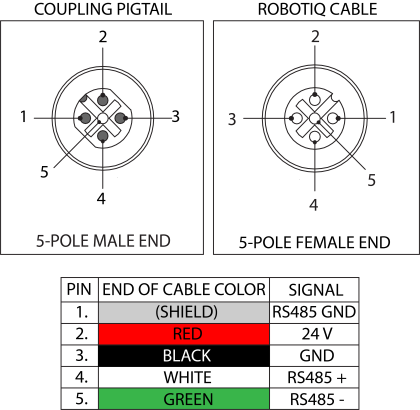
Table 3-2: Pinout of the Hand-E Gripper pigtail and device cable.
If additional cables are used, suggested cable specifications are as follows:
Power supply, fusing
Connect the white, green and bare wires to the Robotiq RS485 to RS232 signal converter (ACC-ADT-RS232-RS485) as shown in the figure below.
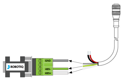
Fig. 3-5: Gripper Cable to RS485/RS232
Also connect the red (24V) and black (0V) wires in the controller according to the figure below.
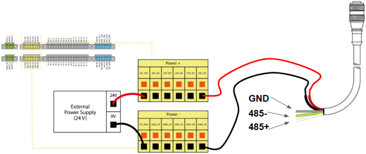
Fig. 3-6: Gripper Cable to Terminal Connector on the Controller
It is possible to connect multiple grippers on the same robot. Only one RS485 to RS232 converter (ACC-ADT-RS232-RS485) should be used. Use M12 splitters (ACC-SPLIT-M12-2:1) to connect all the grippers pigtails to one 10 m cable (CBL-COM-2065-10-HF).
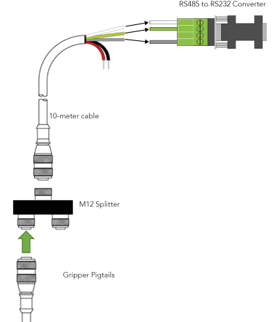
Fig. 3-7: Multiple grippers wiring