Fast Cycle Time
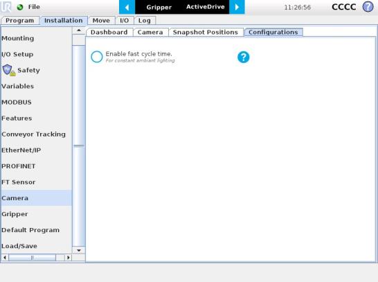
If the ambient lighting is stable during run-time, you can enable the fast cycle time configuration. To do so, go to the Installation tab from the program. Choose Camera and go to Configurations.
Fig. 6-1: Enable fast cycle time when ambient lighting is fixed.
By enabling the fast cycle time configuration, the camera exposure will be set the first time the program enters a Camera Locate node – at runtime. For all other Camera Locate nodes, the camera will keep the exposure settings from the first run. This reduces the cycle time by half as opposed to not enabling the fast cycle time configuration.
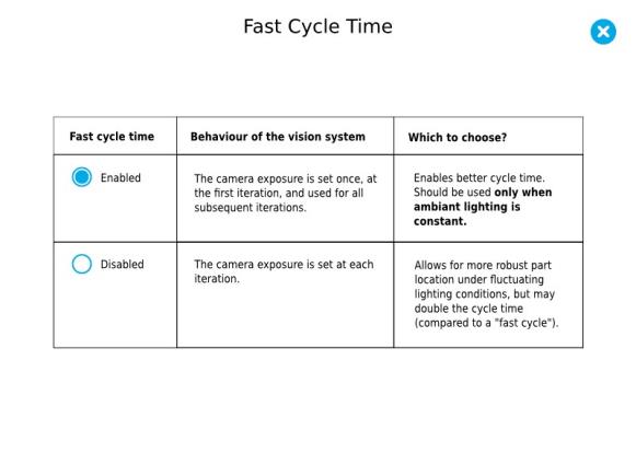
Fig. 6-2: Fast cycle time configuration.
Fast Cycle Time
Enable the fast cycle time configuration only if the external ambient lighting is constant.
Programming
The first thing to do after completing the object teaching is to add a Move node to the Snapshot position. When you exit the object teaching wizard, the robot arm is already in the Snapshot position location. You can simply add a MoveJ command before the Camera Locate node and set it to the location the robot arm is at (see Snapshot_pos_1 from the next figure).
Caution
Make sure the robot arm is moved to the snapshot position before the Camera Locate node in the robot program.
The Camera Locate node acts as an "if" statement. If the taught object is detected by the camera, the robot program will enter in the Camera Locate node and execute all the command lines within it.
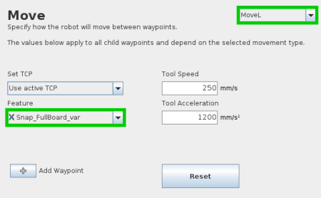
After teaching the object within the Camera Locate node, you may continue the programming by using either a linear move (MoveL) with the snapshot position's variable as feature or the object_location pose. It is also possible to edit the detection threshold or the saved object position after the Teach Object wizard.
Cycle Time
The Camera Locate node cycle time is influenced by the background complexity, the object's features complexity and the number of objects on the workplane.
To reduce the Camera Locate cycle time, consider the following:
Once the Teach Object wizard is completed, you saved the last position of your object. The object position variable, named after the snapshot position, now contains the reference frame of the object in this saved position. Each time the Camera Locate node localizes an object, it updates that feature variable's frame with the new detected object's position and orientation. That feature is named according to the feature name you chose during the snapshot position definition.
Saved position
The saved object position from the Teach Object wizard or the Test/Save wizard is the position of the object to be used for the relative robot motion programming. Once the position is saved, do not move the object to ensure proper robot motion programming within the Camera Locate node.
You can use that reference feature inside the Camera Locate node within Move commands of the robot. To do so:
Every waypoint inserted within that MoveL node will be relative to the feature updated by the Camera Locate.
Once a snapshot position is defined, the workplane used for the calibration gets its own coordinate system, regardless of its orientation. This coordinate system is shown in the figure below.
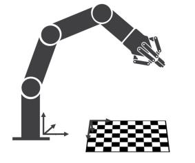
Fig. 6-3: workplane reference frame.
The camera will detect an object on the workplane and find its X-Y position, as well as its Z-orientation in the workplane's coordinate system (see figure below). Thus, a detected object is always laid flat (parallel) to the workplane. It is possible to use the object_location pose, which is a variable containing the detected object's pose (p[x, y, z, x rotation, y rotation, z rotation]) in the robot's base reference frame. This variable is updated each time the program goes within a Camera Locate node, thus every time an object is detected, regardless of how many Camera Locate nodes are in the program. The object_location pose is relative to the robot's base frame.
Info
object_location is a variable containing the detected object's position and orientation relative to the base reference frame. The orientation is always parallel to the workplane on which the calibration has been performed. Thus, the object's X and Y axes are always parallel to the workplane. The Z axis is always normal to the workplane and points downwards from it, into the workplane (refer to the figure below).
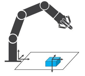
Fig. 6-4: object_location pose on the workplane used for the calibration.
object_location is a variable with the pose structure (x, y, z, x rotation, y rotation, z rotation):
x: x position of the object detected, relative to the robot's base reference frame.
y: y position of the object detected, relative to the robot's base reference frame.
z: z position of the object detected, relative to the robot's base reference frame.
x rotation: x rotation from the robot's base frame to the detected object feature reference frame. The object's X axis is parallel to the workplane on which the calibration has been performed.
y rotation: y rotation from the robot's base frame to the detected object feature reference frame. The object's Y axis is parallel to the workplane on which the calibration has been performed.
z rotation: z rotation from the robot's base frame to the detected object feature reference frame. The object's Z axis is normal to the workplane on which the calibration has been performed, points downwards from it, into the workplane.
If you move the robot's TCP to the object_location pose, the TCP will go and point the object on the workplane. The height value of the object on the workplane should not be taken into account - the TCP might be directly on the object when moving it to the object_location pose.
Program Example
The program examples below show how to use the object_location pose variable.The first one simply moves the robot so that the TCP goes directly on the detected object. Make sure the TCP is set properly to avoid collisions.
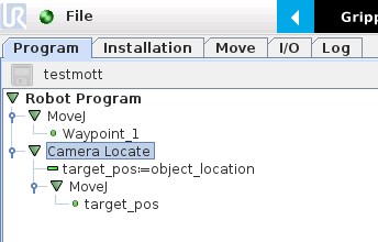
Fig. 6-5: Program example - place the TCP on the detected object.
The second example moves the robot so that the TCP goes 20 cm above the detected object. This is in the case of an horizontal plane.
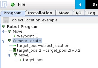
Fig. 6-6: Program example – Place the TCP 20 cm above the detected object, in case of an horizontal plane.
It is possible to edit both the detection threshold and the object location after the Teach object wizard has been completed. To do so, select the Cam Locate node, go to the Command tab and tap Test/Modify.
During a robot program, the robot must be at the snapshot position before entering the Camera Locate node. If it is not in the right position, a pop-up will appear, preventing the camera from taking a snapshot from the wrong position. This is to ensure good precision since the workplane has been previously calibrated for this snapshot position.
In some cases, it is helpful to move the robot to a variable position to enter a Camera Locate node. For instance, it can also used to teach only one snapshot position and object to manage parts in stacked trays. In order to do so, allow the robot to be in a different position that the original snapshot position by entering the script command:
ignore_snapshot_position = True
You also need to edit the snapshot_position_offset pose variable. This variable contains the pose offset between the original saved snapshot position and the one used in the program .
Info
Please note that the arguments of the snapshot_position_offset parameter are expressed in the robot base reference frame.
The example shows a program using a Camera Locate node to manage parts in stacked trays.
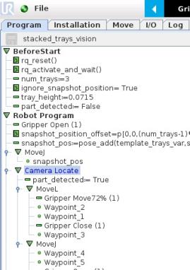
Fig. 6-7: Program example.
ignore_snapshot_position = True
When using this method, make sure the workplane has the same orientation and distance regarding the position of the camera before a Camera Locate node. Using a variable and relative snapshot position may decrease the precision, as the workplane can be slightly different depending on where the calibration has been performed. Be aware of this when programming a Camera Locate node relative to another one.