Caution
The following manual uses the metric system, unless specified, all dimensions are in millimeters.
The following sub-sections provide data on the various specifications for the Robotiq 2-Finger 85 and 140 Adaptive Grippers.
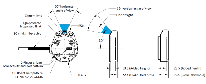
Fig. 7-1: Wrist Camera's dimensions.
|
Specification |
Value |
|
|---|---|---|
|
Maximum load |
10 kg |
40 Nm |
|
Weight (without tool plate) |
160 g |
|
|
Weight (with tool plate) |
230 g | |
|
Added height (without tool plate, for use with 2-Finger Gripper) |
13.5 mm |
|
|
Global thickness (without tool plate) |
22.4 mm |
|
|
Added height (with tool plate) |
23.5 mm |
|
|
Global thickness (with tool plate) |
29.5 mm |
|
Photographic sensor
Respecting Universal Robots's axes system, the photographic sensor's is located at [0mm; 35.7mm; -0.1mm] of the tool flange on which the camera is mounted. The line of sight passes through this point and is at 30° from the Z-axis.
The coordinate system used to calculate the moment of inertia and center of mass of the Wrist Camera is the base of the Camera which correspond to the UR tool flange reference [0,0,0].
Here is the approximate position for the center of mass. It has been calculated for the camera itself and for combinations with other Robotiq products. The camera's tool plate is included when the gripper is not mounted on the Wrist Camera.
|
Combination |
x (mm) |
y (mm) |
z (mm) |
Mass (grams) |
|---|---|---|---|---|
|
- |
0 |
5 |
9 |
230 |
|
FT 300 |
0 | 2 |
30 |
530 |
|
2-Finger 85 |
0 | 1 |
58 |
975 |
|
2-Finger 140 |
0 |
1 |
66 |
1040 |
|
FT 300 and 2-Finger 85 |
0 |
1 |
77 |
1275 |
|
FT 300 and 2-Finger 140 |
0 |
1 |
85 |
1340 |
Here is the approximate moment of inertia matrix for the Wrist Camera:
|
Inertia Matrix |
Metric value |
Imperial value |
||||||
|---|---|---|---|---|---|---|---|---|
|
lxx |
lxy |
lxz |
111 |
0 |
0 |
0.38 |
0 |
0 |
|
lyx |
lyy |
lyz |
0 |
70 |
3 |
0 |
0.24 |
0.01 |
|
lzx |
lzy |
lzz |
0 |
3 |
165 |
0 |
0.01 |
0.56 |
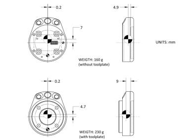
Fig. 7-2: Center of Mass with and without the toolplate.
Robotiq recommends you supply the Wrist Camera from the Universal Robots controller power supply as shown in the Electrical Setup section; if for any reasons you cannot do so, here are the electrical specifications of the Camera:
|
Specification |
Value |
|---|---|
|
Operating supply voltage |
24 V DC ±20% |
|
Quiescent power (minimum power consumption) |
1 W |
|
Maximum power |
22 W |
|
Communication interface |
USB 2.0 |
Here are the Wrist Camera's specifications:
|
Specification |
Value |
|---|---|
|
Maximum resolution |
5 Mpx at 2 fps (2560 X 1920) |
|
Maximum frame rate |
30 fps at 0.3 Mpx (640 X 480) |
|
Active array size |
2592 X 1944 |
|
Focus range |
70 mm to infinity |
|
Integrated lighting |
6 LED diffuse white light |
|
Autofocus technology |
Liquid lense |
Accuracy
The accuracy of the vision system is as described in the table below and depends on the robot model used. It is valid for the area where the calibration board was located during the calibration process.
|
Robot Model |
Accuracy |
|---|---|
| UR3 | +/- 2mm |
| UR5 | +/- 3mm |
| UR10 | +/- 3mm |
Fig. 7-3: Accuracy of the vision system.
Calibration board position

Fig. 7-4: Calibration board position.
|
Specification |
Value |
||
|---|---|---|---|
|
UR3 |
UR5 |
UR10 |
|
| Minimum board distance (cm) | 26 | 34 | 42 |
| Maximum board distance (cm) | 42 | 70 | 98 |
Tips
Snapshot Position will determine the field of view, notice that the calibration step position does not have to be the same as Snapshot position. Thus, you can have a small field of view, then move back for calibration step.
Field of view
Camera field of view depends on the distance between the workplane surface and the camera. The table below shows the field of view of the camera depending on the Universal Robot used.
|
|
UR3 |
UR5 |
UR10 |
|||
|---|---|---|---|---|---|---|
|
Distance* (cm) |
FoV (cm) |
Distance* (cm) |
FoV (cm) |
Distance* (cm) |
FoV (cm) |
|
| Maximum** | 34.7 | 36 x 27 | 64.6 |
64 x 48 |
103.0 |
100 x 75 |
| Minimum** | 7 | 10 x 7.5 | 7 |
10 x 7.5 |
7 |
10 x 7.5 |
*Workplane surface to camera distance (considering the workplace surface at the same level as the robot base).
**For indication only, larger field of view is possible depending on robot mounting configuration and parts locations. Contact Robotiq support if more information is required.
Table 7 - 4: Camera field of view depending on the robot's reachable area.
Info
Field of view is (FoV) determined by Snapshot position. To get the minimum FoV, the camera must be placed at 7 cm above the work plane.
Part dimensions
The maximum part size that can be detected by the Wrist Camera is 60% field of view's dimension. The minimum is 10%, no matter the robot or the field of view size.
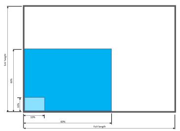
Fig. 7-5: Maximum and minimum part size.
The part must not be higher than its smallest dimension (width or length) : maximum of 1:1 ratio.

Fig. 7-6: Maximum part height.
Info
Part height ratio is taken between the maximum part height at any point and the minimum dimension present on part contour, width or length.
Background contrast
To ensure a good model and part detection from the Vision system, you should use a background that has a high color contrast with the part to be detected. You must choose colors that are apart horizontally on the HSV cone shown below. Therefore, a change in value (intensity) only does not represent a good contrast. There has to be a great difference in hue and saturation to obtain a good object model from the object teaching wizard. You can use either the yellow or pink side of the colored background provided with the camera kit. If required, use a different colored background to teach your part.
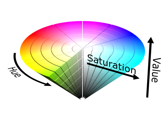
Fig. 7-7: HSV color cone.