5. Object Teaching
Once the snapshot position is defined (see section 4), the operator can use the Camera Locate node within a Universal Robot program to teach an object to locate. The following section and sub-sections will guide you through this process.
Requirements
- You must have completed the installation steps of section 3.
- Snapshot position is defined as per steps of section 4.
- Have the object to teach in hand:
- Have a few samples to test during the last step of the object teaching process.
Reminder
- A Camera Locate node will be used for a single model.
- Object teaching is linked to the snapshot position, if you want to change snapshot position, you will have to perform the object teaching again.
- You can teach many objects; each one will use a Camera Locate node.
Background
- Have a background that provides a maximum of contrast with your object, see section 4.1 for guidelines.
Tip
A colored background is provided with the camera kit. Use either the yellow or pink side to ensure a good color contrast with the object.
5.1. Guidelines on Object Teaching
Info
During the object teaching, the ambient light must be approximately 500 lux, and stable.
At runtime, this condition is not required.
The following must be considered when going through the object teaching process :
- Objects criteria for reliable localization:
- Object is quasi-flat, respecting a maximum ratio of 1:1 between its height and its smallest dimension; please refer to the Vision System Specifications section for more details.
- Top surface is mostly flat.
- Object has a distinctive shape and distinctive features.
Info
Distinctive shape would mean an object contour that displays a sharp contrast with the background, and that is ideally not symmetric. Distinctive features are shapes present within the contour of the object that the vision system will be able to identify, such as holes, drawings, color contrasts, etc.
- Object is not highly reflective
- Object is not transparent
Tip
When teaching reflective objects, the user can turn the LEDs OFF to avoid bright spots contrasting with the actual color of the object.
- Choosing the appropriate background:
- Workplane around the object must be planar, mostly uniform and clear of any other objects.
- At runtime, the work space conditions can change, the object detection threshold can be used to adjust detection settings according to those conditions; refer to the Detection thresholds and scores section for details.
- The background around the object must be a uniform, continuous shape with a single color.
Caution
From the vision system's point of view, white, gray and black are all gradients of gray. Avoid using a black background to teach metal objects. The model would be a pale gray object on a dark gray background and would therefore result in errors.
The Machine edge view feature shows edges seen by the camera in greyscale format. Please refer to the Teach Object Wizard section for more details. Refer to the Vision System Specifications section for specifications on color contrast.
Tip
At runtime, make sure you have the simplest and most uniform background possible for your application. Also have as few objects and object types as possible. This will decrease the cycle time.
Tip
The ambient light should be diffuse. Avoid high light intensity spots on your background. This will result in a faster object detection by the Wrist Camera and a lesser risk of false detection.
5.2. Teach Object Wizard
Camera Locate Node
To insert a Camera Locate node in the robot program, from the Universal Robots PolyScope interface:
- At the top of the screen, tap the New icon to create a program or the Open icon to load a program.
- Select Program. The Program window will display.
- Tap the URCaps menu in the navigation pane on the left.
- Tap the Cam Locate button.
- Select the node in the robot program and tap the Command tab.
- Tap the Edit action button to edit the node's parameters.
Teach Object Wizard
Info
Snapshot position must be defined to launch the object teaching wizard. If not, go to section 4.
The Teach object wizard will guide you through the process of teaching an object for locating with the camera. Select the Cam Locate node, go to the Command and tap Teach object to launch the wizard.
Choose teaching method
The first step is to choose the teaching method. Choose between either the automatic or parametric method:
-
Automatic method: builds a model based on photos and a scan of the object. Best for complex and irregular shapes. Use this method if the object orientation has to be detected with one of its features. Please refer to the Automatic Method section for more details.
-
Parametric method: builds a model based on parameters of a basic 2D shape (circle, ring, square or rectangle). This method is faster and allows the vision system to recognize and locate with high robustness objects that have few distinctive features such as raw material blanks. Usually gives best results than the Automatic method for simple geometry and highly reflective objects. Please refer to the Parametric Method section for more details.
Tip
At any moment during the teaching process, the user can access contextual help videos with the Play button.

|
Play button that displays contextual help videos for visual support in going through the teaching steps
|

|
Question mark button that displays an HTML version of the Wrist Camera's instruction manual directly on the teach pendant (feature to be implemented in the near future)
|
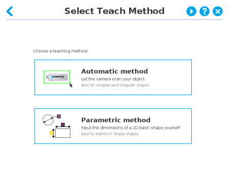
Fig. 5-1: Selection of the teaching method.
5.2.1. Automatic Method
Caution
A Snapshot position must be defined to launch the object teaching wizard. If no Snapshot position has been defined, please refer to the Snapshot Position section.
5.2.1.1. Select Calibration
Tip
At any moment during the teaching process, the user can access contextual help videos with the Play button.
Tap the Snapshot position you want to use.
Info
If the robot is not at the Snapshot position, you will be prompted to move to the position.
Tap and hold the Move button to do so.
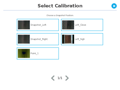
Fig. 5-2: Select Calibration step
5.2.1.2. Select Model
Tip
At any moment during the teaching process, the user can access contextual help videos with the Play button.
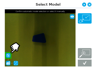
Prior to selecting a model, the user will place a background on the workplane and then position the object on the background. By default, the Select Model step displays the object to teach, automatically selected by the software, meaning a green selection rectangle overlaps the shape of the object.
Automatic area selection
The object is selected since the Magic Wand tool is enabled by default. The Magic Wand feature allows to locate objects on the background without user intervention.
Info
For the automatic area selection feature to function properly, the user has to employ a uniform background, and a single object with well defined edges.
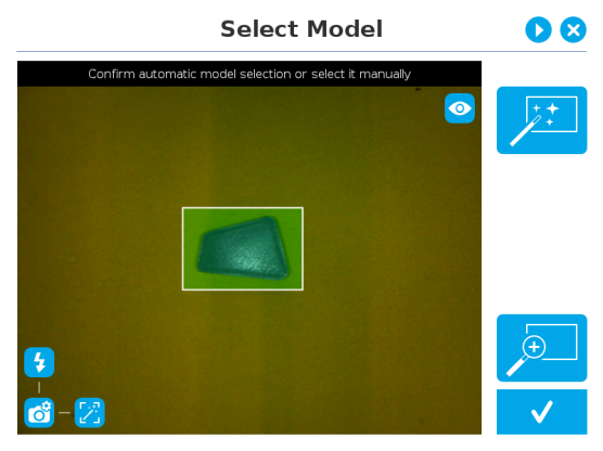
Fig. 5-3: Select Model step with object automatically selected by the Magic Wand tool
Tip
Tapping the Magic Wand tile in the right pane of the PolyScope interface switches the area selection mode to Manual.
Manual area selection
The user then selects an area by tapping the screen and dragging his/her finger to contain the desired object in the selection area.
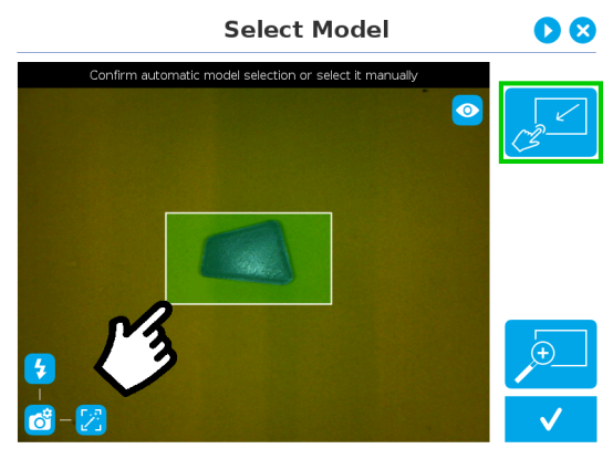
Fig. 5-4: Select Model step with Manual area selection feature
Tip
The manual area selection is useful for careful inspection of specific features using the zoom function.
Refer to the Zoom section for more details.
The manual area selection can also be used for partial custom object selection (i.e. for selecting standalone features or components of an object).
Tip
Tapping the Manual selection button in the right pane will bring back the Automatic area selection mode.
Camera views
Standard view
When in standard view mode, the camera feed displays a reasonably faithful image based on what is normally perceived by the human eye (colored object on colored background).
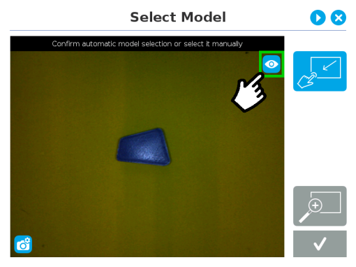
Fig. 5-5: Select Model step with standard view enabled
Tip
Tapping the eye button in the upper right corner of the camera feed window will bring up the machine view.
Machine edge view
The user can access the machine view by tapping the Color view button in the upper right corner of the camera feed window. The machine view makes no discrimination between colors; it rather highlights the contour of the selected object.
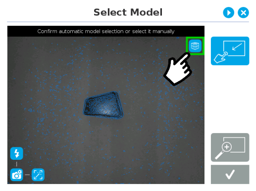
Fig. 5-6: Select Model step with Machine edge view enabled
Tip
The Machine edge view is a convenient tool that can be used to better understand the quality of the image and the object contrast, and to improve adjustments made to the selection.
Tip
Tapping the cube button in the upper right corner of the camera feed window will bring up the Machine color view.
Machine color view
The user can access the Machine color view by tapping the Machine edge view button in the upper right corner of the camera feed window. The Machine color view displays the elementary colors perceived by the vision system.
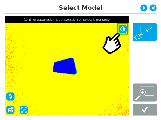
Fig. 5-7: Select Model step with Machine color view enabled
Tip
The Machine color view is a convenient tool that can be used to better understand the color signature and scale used by the system.
Tip
Tapping the drop button in the upper right corner of the camera feed window will bring up the standard view.
Camera settings
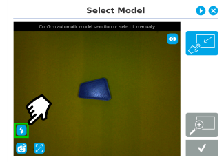
In order to access the advanced camera settings, tap the camera/gear icon in the lower left corner of the camera feed.

|
Camera settings
|

|
Camera LEDs are ON; please refer to the Camera LEDs section for more details.
|

|
Camera LEDs are OFF; please refer to the Camera LEDs section for more details.
|

|
Automatic focus is enabled; please refer to the Focus section for more details.
|

|
Manual focus is enabled; please refer to the Focus section for more details.
|

|
Shallow focus button; please refer to the Focus section for more details.
|

|
Deep focus button; please refer to the Focus section for more details.
|
Camera LEDs
|
|
|
Camera LEDs ON
|
Camera LEDs OFF
|
Tip
The LEDs, when turned ON, sometimes highlight undesirable features or create reflections that distort the teaching process. It is recommended to try both settings when teaching the object in order to select the most conclusive result.
Warning
The flash and focus settings selected will be used at runtime unless changes are made at the Configure Model step at the end of the teaching process.
Please refer to the Configure Model section for more details.
Focus
Info
Focus features can be used to sharpen or diminish the contrast between the object and the background, and adjust the depth of field. The settings will be captured at runtime except if changes are made to the model during the Configure Model step. Please refer to the Configure Model section for more details.
Automatic focus
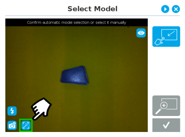
Fig. 5-8: Select Model step with automatic focus option enabled
To some extent, the automatic focus feature detects sharpness in the overall image. If the image is blurry, the autofocus system will adjust the focus until sharpness and/or contrast is achieved. This type of automatic focus requires enough contrast between the object and the background for it to render an appropriate image.
Manual focus
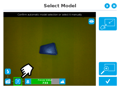
Fig. 5-9: Select Model step with manual focus option enabled
The manual focus feature allows the user to adjust the depth of field. Tapping the flower button reduces the focus value, making the depth of field narrower, while tapping the mountain button increases the focus value, making the depth of field deeper.
Zoom
The zoom-in/zoom-out tool is used to toggle between a high-level view and a more explicit view of the selection area (and object).
Zoom in
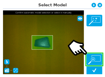
Fig. 5-10: Select Model step with Zoom in button highlighted
In order to zoom in on the selection area, the user has to tap the magnifier with a plus symbol in the lower right corner of the teach pendant interface.
Once zoomed in, the user can perform focus adjustments to improve the recognition of edges in the model.
Info
Note that when zoomed in, the user can neither change the area selection mode nor accept the model selected (the buttons are greyed out). The zoom in feature is therefore solely used for inspecting the model in details and for adjusting the depth of field via the manual focus settings.
Zoom out
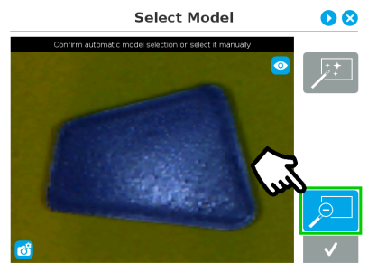
Fig. 5-11: Select Model step with Zoom out button highlighted
In order to zoom out from the selection area, the user has to tap the magnifier with a minus symbol in the lower right corner of the teach pendant interface.
Accepting the model
When the view of the model selected is satisfactory and you wish to carry on with the teaching wizard steps, tap the button with the check mark in the lower right corner of the teach pendant interface.
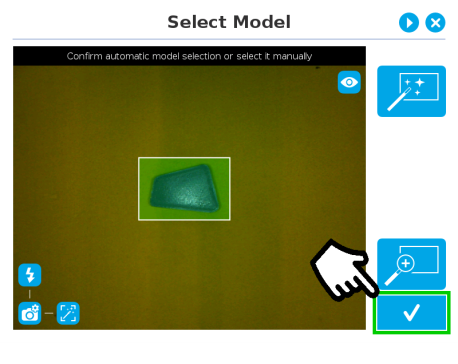
Fig. 5-12: Select Model step with Accept button highlighted
5.2.1.3. Edit Model
Tip
At any moment during the teaching process, the user can access contextual help videos with the Play button.
Right after accepting the model at the end of the Select Model step, the camera automatically zooms in on the object selected. Quick selection modes and tools are made available to the user.
Info
The user can alternate between color and machine view while editing the model. Please refer to the Camera views section for more details.
Quick selection modes
Tap the arrow to the left of the quick selection tool to expand the selection modes menu.
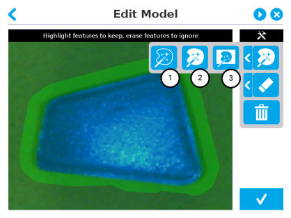
Fig. 5-13: Edit Model step with quick selection modes expanded
-
Outline only
The Outline only selection tool is used to highlight the contour of the object
Info
The selection area bleeds off the edge of the object to capture the background color.
Caution
The Outline only selection tool is not available for an object that has been selected manually at the Select Model step. This prevents users from selecting the partial contour of an object, which could lead to faulty contrasts and edge detection.
-
Outline & surface
The Outline & surface selection tool is used to highlight the contour and upper surface of the object. Tap the middle button. This tool is selected by default when the user accepts a model selected automatically during the Select Model step.
Info
The selection area bleeds off the edge of the object to capture the background color.
Caution
The Outline & surface selection tool is not available for an object that has been selected manually at the Select Model step. This prevents users from selecting the partial outline and/or surface of an object, which could lead to faulty contrasts and edge detection.
-
Rectangle around object
The Rectangle around object selection tool generates a rectangular selection area surrounding the object.
Info
The Rectangle around object selection tool is automatically selected when the object has been manually selected at the Select Model step. The other options are disabled. This prevents users from selecting a partial outline and/or surface of the object, which could lead to faulty contrasts, and erroneous color signature and background identification.
Tools
Tap the arrow to the left of the tools button to expand the tools menu.
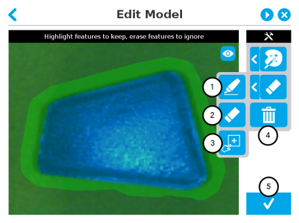
-
Marker
The marker tool can be used to highlight features and edges to include and keep in the selection area.
Slide your finger or pointing device on the desired area(s) on the teach pendant. A green object layer mask will be applied to the highlighted portion of the model.
-
Eraser
The eraser tool can be used to ignore features and edges in the selection area.
Slide your finger or pointing device on the undesired area(s) on the teach pendant. The object layer mask will be replaced by the background layer mask.
-
Rectangle+ (add area)
The rectangle+ (add area) tool can be used to quickly highlight desired areas.
Tap and drag your finger or pointing device to draw rectangular shapes that will highlight presently available features.
Deleting the selection area
-
Garbage can
Tapping the garbage can icon will clear the object layer mask, thus deleting the selection area.
Accepting the model
-
Check mark
When the view of the model is satisfactory and you wish to carry on with the teaching wizard steps, tap the button with the check mark in the lower right corner of the teach pendant interface.
Caution
Tapping the Accept model button (check mark) takes a picture of the model that will act as the first step in the next phase of the teaching process: Refine Model.
5.2.1.4. Refine Model
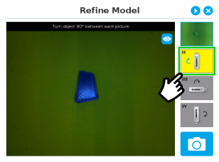
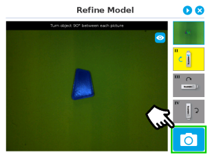
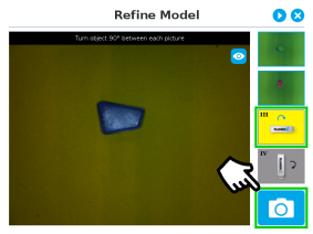
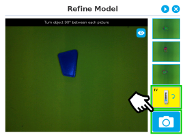
The Refine Model step prompts the user to take photos of the model in four different orientations. The purpose of this step is to remove shade effects associated with the edges of the object in order to refine the model.
Info
The first photo is automatically generated at the end of the Edit Model step.
Info
Tap the camera icon to take a photo between each step. An error will pop up if the object has not been rotated.
|
|
|
1. The user is prompted to turn the object 90 degrees clockwise. Note that the first picture is already taken, in the upper right corner.
|
2. The user is prompted to take the second picture of the object.
|
|
|
|
3. Object turned another 90 degrees clockwise. The user is prompted to take the third picture.
|
4. Object turned another 90 degrees clockwise. The user is prompted to take the fourth picture.
|
Tip
Tap on any snapshot taken in the object teaching wizard to enlarge it.
5.2.1.5. Validate Model
Tip
At any moment during the teaching process, the user can access contextual help videos with the Play button.
The Validate Model step will start right after the fourth picture is taken at the end of the Refine Model step.
Info
If the object is properly detected, it will display green and red outlines.
If the object has not been recognized, please refer to the Guidelines on Object Teaching section for instructions.

|
Accept button
|

|
Retake button
|
The Validate Model step is used to verify the contour selection of the model. If satisfactory, the user can accept the model by pressing the Accept button, or go through the Refine Model step again by tapping the Retake button.
Main points to observe:
- Object contours and detected features are outlined in green
- Features from the model that cannot be located on the object in the field of view of the camera are outlined in red.
5.2.1.6. Scan Model
Tip
At any moment during the teaching process, the user can access contextual help videos with the Play button.
Warning
Scanning is an automatic process; the robot will move in order to perform calibration. Make sure the robot's work space is clear. You can tap Cancel to stop the process. The operator should watch the robot at all time and have the emergency stop button at hand.


|
Scan button used to start the scanning process
|
|
Cancel button used to abort the scanning process while it is running
|
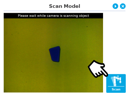
Fig. 5-14: Scan Model step with Scan button highlighted
The vision system will run a scan of the object by taking 9 pictures.
When the process is completed, the wizard will bring up the Configure Model step. Please refer to the Configure Model section for more information.
5.2.2. Parametric Method
When teaching a simple geometry object, it is recommended to use the Parametric method. It builds a model based on parameters of a basic 2D shape (circle, ring, square or rectangle). This method allows the vision system to recognize and locate with high robustness objects that have few distinctive features such as raw material blanks. It usually gives best results than the Automatic method for simple geometry and highly reflective objects.
Choose the geometry that corresponds to the object to detect and define its parameters:
- Circle
- Ring
- Rectangle
- Square
Caution
In all cases, the height (h) is the distance between the workplane and the 2D shape. It considers and compensates the thickness of the provided calibration board (roughly 3mm) that was used to calibrate the workplane.
Thus, if you calibrated the workplane using a printed version of the calibration board, you must add 3mm to the height measurement.

|
Define button used to confirm the dimensions of the object.
|
5.2.2.1. Circle
Tip
At any moment during the teaching process, the user can access contextual help videos with the Play button.
Enter the circle diameter (D) and the height (h) at which the circle is located. Tap the Define button.
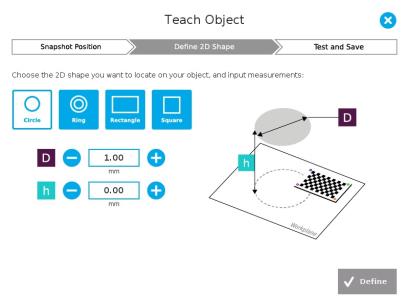
Fig. 5-15: Definition of a circle 2D shape.
5.2.2.2. Ring
Enter the ring outer diameter (D), inner diameter (d) and the height (h) at which the ring is located. Tap the Define button.
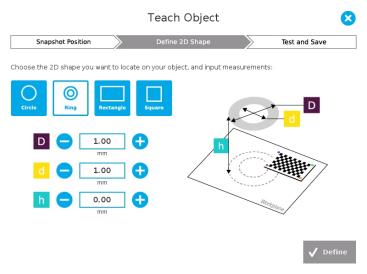
Fig. 5-16: Definition of a ring 2D shape.
5.2.2.3. Rectangle
Enter the rectangle length (l), width (w) and the height (h) at which the rectangle is located. Tap the Define button.
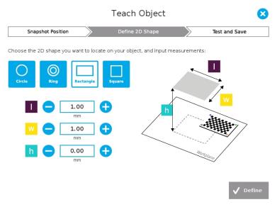
Fig. 5-17: Definition of a rectangle 2D shape.
5.2.2.4. Square
Enter the square length (l) and the height (h) at which the square is located.
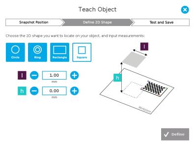
Fig. 5-18: Definition of a square 2D shape.
When the process is done, the wizard will switch to the Configure Model step. Please refer to the Configure Model section for more details.
5.2.3. Configure Model

|
Test locating object button; the Vision System will search for the object in the field of view of the Wrist Camera.
|

|
Back button; after testing an object's location, tap to return to the output image of the camera.
|
|

|
Color validation button; tap to open the color validation menu.
A colored button Indicates that the color validation mode is enabled.
Please refer to the Color Validation section for more details.
|
|

|
|
Multiple Object Detection button; a grey button means the feature is not available at the moment.
Tap to open the multi-object detection menu.
|

|
|

|
Detection Threshold button; tap to expand the detection threshold menu. Please refer to the Detection thresholds and scores section for more details.
|
|

|
Minus button; tap to lower the Detection Threshold. Please refer to the Detection thresholds and scores section for more details.
|
|

|
Plus button; tap to increase the Detection Threshold. Please refer to the Detection thresholds and scores section for more details.
|
|

|
Camera settings button; please refer to the Camera settings section for more details.
|
|

|
Score value box; display section in which the detection score appears after testing the object location.
|
|

|
Object location button; when an object is found, tap this button to view its position relative to the robot base.
|
|

|
Set reference position button; tap to save the object's position for programming linear move (MoveL) relative to the object's location. Please refer to the Save location section for more details.
|
|

|
Save & finish button; tap to save the detection threshold, the reference position and finish the wizard.
|
|

|
Test/Modify button; accessible via the Command tab of the Program Robot interface in Polyscope, once the object teaching wizard is completed. Tap to access the Test and Modify wizard. It allows the user to modify the detection threshold and the saved object position.
|
|

|
Reset button; accessible via the Command tab of the Program Robot interface in Polyscope, once the Teach object wizard is completed. Tap to reset the whole process of the object teaching wizard.
|
5.2.3.1. Multiple objects detection
In order to enable the multiple objects detection, tap the multi-object button from the Configure Model step.
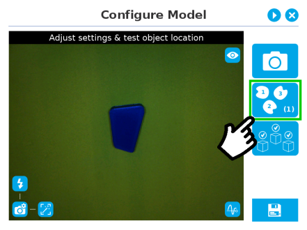
Fig. 5-19: Configure Model with multi-object button highlighted.
Once in the multi-object menu, tap the plus (+) symbol to increase the maximum number of objects to detect, or tap the minus (-) symbol to reduce that number.
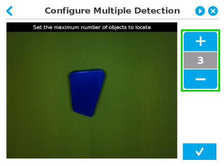
Fig. 5-20: Configure Multiple Detection menu.
5.2.3.2. Color Validation
Color validation adds reliability to the camera locate feature.
Whereas editing the model allows to select, configure and save the shape, outline and area of the model, the color validation allows the system to save the color signature of objects or features.
Warning
Color validation is not intended for discriminating between two colors in the same Camera Locate node, no matter what the purpose is. However, this action can be performed and programmed with two or more Camera Locate nodes in the same program tree.
Color validation is not intended for eliminating all colors but one in a Camera Locate node, no matter what the purpose is.
Automatic method
- Tap the color validation button to access the color validation menu
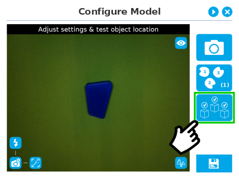
Fig. 5-21: Configure Model with color validation button highlighted.
- Turn on color validation by tapping the red button on the right side of the screen.
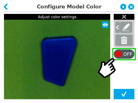
Fig. 5-22: Configure Model Color model with ON/OFF button highlighted
Color sampling tools
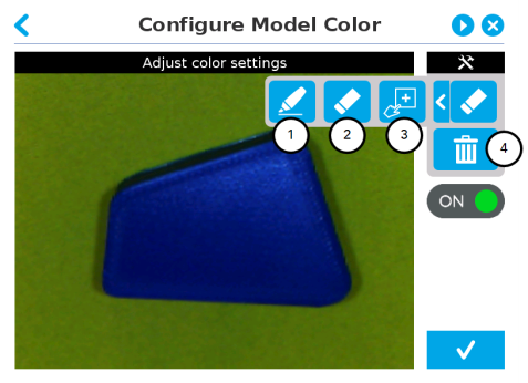
-
Marker
The marker tool can be used to highlight features and edges to include and keep in the color sampling area.
Slide your finger or pointing device on the desired area(s) on the teach pendant. A green layer mask will be applied to the highlighted portion of the model.
-
Eraser
The eraser tool can be used to ignore features and edges in the color sampling area.
Slide your finger or pointing device on the undesired area(s) on the teach pendant.
-
Rectangle+ (add area)
The rectangle+ (add area) tool can be used to quickly highlight desired areas for color sampling.
Tap and drag your finger or pointing device to draw rectangular shapes that will highlight available features.
- Garbage can
Tapping the garbage can icon will clear the object layer mask, thus deleting the selection area.
Info
The validation routine of the camera is performed in two steps:
- Contour (edge) validation, with its own detection score
- Color validation (if applicable), with its own detection score
Tip
Using the color validation helps to avoid false detections in your background.
Parametric method
- Tap the color validation button to access the color validation menu.
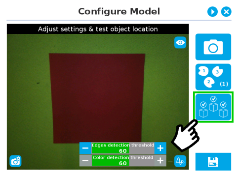
Fig. 5-23: Configure Model Step (Parametric method) with color validation button highlighted.
- Turn on color validation by the tapping the red button on the right side of the screen.
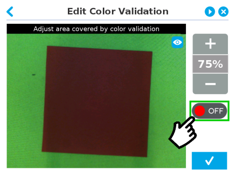
Fig. 5-24: Edit Color Validation menu (Parametric method) with ON/OFF toggle button highlighted.
Color sampling tool
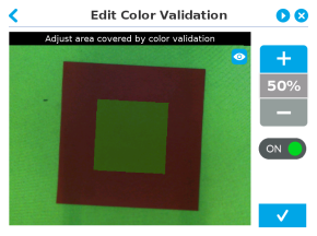
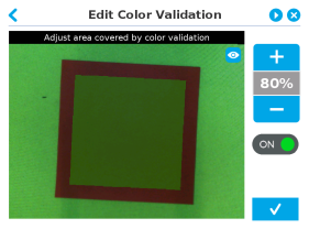
In the parametric method, given the inherent symmetry of the objects located by the system, color validation is supported via an expendable/shrinkable color selection zone, on par with the contour of the object to be located.
Tap the plus icon to expand the color selection zone, and tap the minus button to shrink the selection zone.
|
|
|
Color selection zone (50% of object size)
|
Color selection zone (80% of object size)
|
Caution
The size of the color selection zone ranges from 50% of the object size to 150% of the object size.
5.2.3.3. Detection thresholds and scores
At the Configure model step, the user can tap the Detection threshold button in the lower right corner to expand the detection threshold settings.
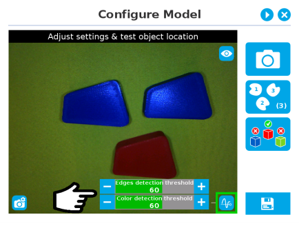
Fig. 5-25: Configure Model Step with detection thresholds highlighted.
After adjusting the detection thresholds, if applicable, the user can test the location of the object(s) in the field of view by tapping the camera icon.
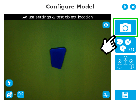
Fig. 5-26: Configure Model Step with camera icon highlighted.
Info
In the context of multiple objects detection, each object detected has its own set of detection score values (%).
Edges detection threshold and score
If the object is found, you will see the object outlined, surrounded by a blue rectangle, with the detection score value (%).
Other objects detected will be surrounded by a white rectangle. Tap the other object(s) to display their own set of detection score values.
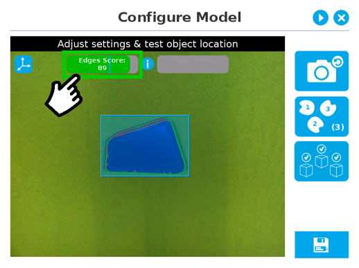
Fig. 5-27: Object found with detection score.
- If no object is found, an error message will display, reading that the object was not found.
When testing the object(s) locating:
- Object contours and detected features are outlined in green
- Features from the model that cannot be located on the object in the field of view of the camera are outlined in red.
Info
In the context of multiple objects detection, each object detected has its own set of detection score values (%).
Info
When performing the localization test, place the whole object over the workplane. Due to the perspective effect, some or all of the object features might not be recognized. If an important feature needs to be found for your application (a hole for example), make sure it is found during all localization tests. Again, green contour should match the object outlines at all times.
Tip
To avoid false detections, remove the object from the workplane, decrease the detection threshold to 0% and try to locate the object. If a false detection occurs on your workplane, you will see an object detected with the detection score. Increase the detection threshold above this score to avoid false detection.
- Try all areas of the workplane on which the object might be found. Adjust the detection threshold properly for the object and for the runtime environment.
- Adjust the detection threshold with the plus (+) and minus (-) buttons.
Tip
Set the detection threshold at the highest value possible so the vision system detects the object on the whole workplane. Tap the Test locating object button to test the threshold.
This ensures optimal robustness for object detection everywher on the workplane. If it is not possible to reach such a success rate, the following should be considered:
- Redefine the Cam Locate node (go through the Teach object wizard again), make sure there are no reflections, or as few as possible.
- Refer to the Guidelines on Object Teaching section for instructions
Tip
After completing the object teaching wizard, it is possible to edit the detection threshold. To do so, select the Camera Locate node and go to the Command tab. Click on Test/Modify to edit the threshold and/or modify the position of the object.
Color detection threshold and score
Color detection can only happen following a successful edge detection.
Caution
Color validation must be enabled in order to go through the color detection step. Please refer to the Color Validation section for more details on enabling color validation.
If the object goes through the 2-step detection successfully, you will see the object(s) outlined, surrounded by a blue rectangle, with the detection score values (%).
Other objects detected will be surrounded by a white rectangle. Tap the other object(s) to display their own set of detection score values.
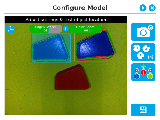
Fig. 5-28: Multiple objects found each with their selection rectangles and detection scores.
Info
In the context of multiple objects detection, each object detected has its own set of detection score values (%).
5.2.3.4. Camera settings
Warning
Camera settings can be adjusted at the Select Model step of the Automatic teaching method and/or at the Configure Model step of the Teach object wizard.
Editing the camera settings at the Configure Model step will override the settings selected at the Select Model step of the Automatic teaching method.
Please refer to the Camera settings section for more details.
5.2.3.5. Save location
Once you are done with the test and adjustment, tap the Set reference position button.
Caution
Do not move the object after saving the position; the subsequent relative movements programmed will be relative to that position. Please refer to the Programming with the Camera Locate Node section for more details.
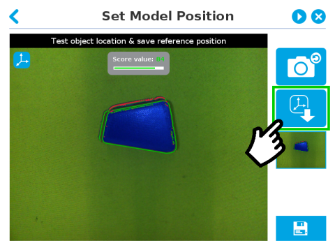
Fig. 5-29: Position defined.
Once the position is saved, tap the Save & Reset button in the lower right corner of the teach pendant interface.
When you are done with the teaching process, the Camera Locate node will show you a snapshot of your saved object. You can tap Reset to redefine completely. You can tap Test / Modify to change the detection threshold or both the threshold and the saved object position.