Prior to teaching object with the Camera Locate URCaps node (refer to the Programming with the Camera Locate Node section), the operator must define a Snapshot Position using the Snapshot Position wizard. The following section and sub-sections will guide you through this process.
Requirements:
Reminders:
Calibration Boards:
Tip
If you are viewing a printed version of this manual, please visit support.robotiq.com to download the file.
Along with your kit you will have the calibration board used for UR5 and UR10 on one side of the board, part number
ACC-CALIB-BOARD.
If you lose or damage your board, you can print the following file:
Note
If you are viewing the PDF version of the manual, please visit the online version of this manual at support.robotiq.com to get the calibration board files. If you have printed this manual, please stop doing so, save some trees and visit the website.
Info
UR5 and UR10 calibration board must be printed on Letter (11'' x 17'') or A3 paper, make sure scale is at 100%. You can validate that your calibration board had the good scale by measuring the scale on your sheet.
Along with your kit you will have the calibration board used for UR3 robots on one side of the board, part number
ACC-CALIB-BOARD. The color balance circles are not used yet with the vision system and are for future use. If you loose or damage your board, you can print the following file:
Info
UR3 calibration board must be printed on Letter (8.5'' x 11'') or A4 paper, make sure scale is at 100%. You can validate that your calibration board had the good scale by measuring the scale on your sheet.
Caution
During the snapshot position definition, the ambient light must be of approximately 500 lux. At run-time, this condition is not required.
Snapshot position used for teaching the object may be different than the one used in production. However, camera angles and distances should be similar.
For example, conveyor areas are often hard to reach, thus causing object scanning issues. You can use a convenient area for object model teaching that will allow easy scanning. It is always possible to modify the final light and threshold adjustments at the runtime area using ignore_snapshot_position = True variable. Please refer toProgramming with the Camera Locate Node section
The following must be considered when choosing your Snapshot Position:
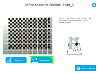
Tip
During the Snapshot Position define step, use the "Show Grid" button, a grid will appear. Your object should be larger than one grid cell.
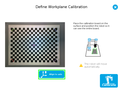
Tip
The Align to axis button can be use to obtain a perpendicular-to-the-surface angle. This button will also align the camera to the base axis of the robot.
Fig. 4-1: Align to axis feature.
Tip
The Snapshot position and Calibration pose are decoupled, they do not need to be the same.
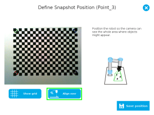
Tip
The Align over button can be used to move the camera over the center of the screen, while keeping it’s height position. The camera also becomes coplanar to the surface but keeps the same orientation.
|
|
| (a) | (b) |
Fig. 4-2: Align over feature; (a) Whitout grid shown (b) With grid shown.
Feature Point:
Prior to defining the Snapshot Position, the operator must define a feature point. To do so, from the Universal Robots Polyscope interface:
Info
Each Snapshot Position you teach will require its own Feature point.
Snapshot Position Wizard:
Snapshot Position is define using the Snapshot Position Wizard, from the Universal Robots Polyscope interface, still within the Installation tab:
Wizard step 1: Define Snapshot Position
Wizard step 2: Calibrate
Tip
Snapshot Position will determine the field of view, notice that the calibration step position does not have to be the same as Snapshot position. Thus, you can have a small field of view, then move back for calibration step.
Warning
Calibration is an automatic process, the robot will move in order to perform calibration. Make sure the robot workspace is clear. You can tap Cancel to stop the process. Operator should watch the robot at all time and have emergency stop button at hand.
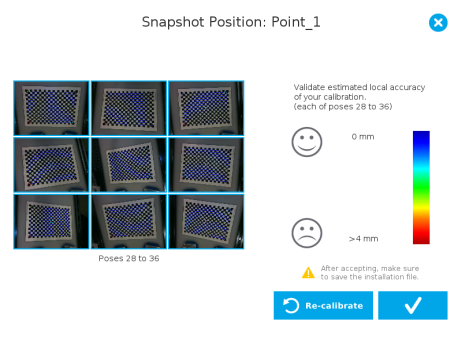
Fig. 4-3: Validating poses.
Once the calibration has been accepted, the Snapshot Position will appear in the Snapshot Positions tab with the name of the Feature Point previously created. You can define other Snapshot positions, as long as you define new Feature Points. To delete a Snapshot Position, tap the bin.
Tip
Make sure you save the Installation file (tap Load/Save from the Installation tab) in order to save the Snapshot positions created.
Features
|
Icon |
Feature |
Description |
|---|---|---|

|
Define |
Launches the Snapshot Position definition wizard. |

|
Show grid |
Displays a grid on the camera's field of view. Meant to test the camera’s height relative to the workplane : a part should be at least as large as a square of the grid. |

|
Hide grid |
Hides the grid of the camera's field of view. |
|
|
Save position |
Saves the robot position for the Snapshot Position. This is the position from which the robot will do the part detection. |
|
|
Calibrate |
Starts the calibration procedure. The robot will move automatically to defined positions for the calibration. |
|
|
Cancel |
Cancels the calibration procedure while it is running. |
|
|
Re-calibrate |
Restarts the calibration procedure. |
|
|
Accept |
Accepts the calibration process. |
|
|
Align to axis |
Aligns the camera to the base axis of the robot. |
|
|
Align over |
Aligns the camera over the center point |
|
|
Delete |
Deletes a defined Snapshot position. |
When defining a snapshot position, it is possible to copy the calibration from another snapshot position. This allows for a faster snapshot position modification when using the same work plane.
Work Plane
To ensure proper precision, the work plane surface of both (new and copied) snapshot positions should be the same.
To copy a calibration, you need to have a snapshot position already defined from which you want to copy the calibration.