Caution
The following manual uses the metric system, unless specified, all dimensions are in millimeters.
The following subsections provide data on the various specifications for the Robotiq 2-Finger 85 and 140 Adaptive Grippers.
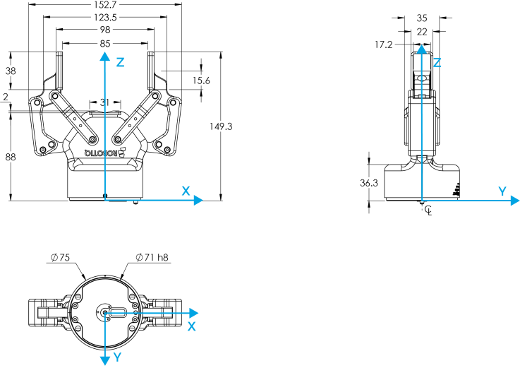
The 2-Finger 85 and 2-Finger 140 share the same basic chassis and thus have the same technical dimensions for everything except the fingers. Figure 6-1 represents the Robotiq 2-Finger 85 Adaptive Robot Gripper's dimensions with axis X, Y, Z and origin referenced for finger motion. Figure 6-3 will show the equivalent with 140 mm fingers (2-Finger 140).
Info
All technical drawings in the present section are shown with silicone flat fingertip option: AGC-TIP-204-085 (2-Finger 85) or AGC-TIP-420-140 (2- Finger 140).
Fig. 6-1: 2F-85 general dimensions (opened).
As mentioned in the figure above, height and width of the fingers vary with opening position. Figure 6-1 represents the 2F-85 Gripper in the opened position (position request = 0), while Figure 6-2 represents the 2F-85 Gripper in the closed position (position request = 255).

Fig. 6-2: 2F-85 dimensions (closed).
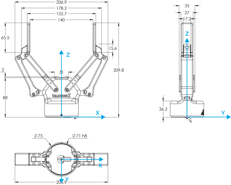
Fig. 6-3: 2F-140 general dimensions (opened).

Fig. 6-4: 2F-140 dimensions (closed).
As mentioned in the figure above, the height and width of the fingers vary with opening position. Figure 6-3 represents the 2F-140 Gripper in the opened position (position request = 0), while Figure 6-4 represents the 2F-140 Gripper in the closed position (position request = 255).
The Robotiq 2-Finger Adaptive Robot Gripper requires a coupling provided by Robotiq to operate. The coupling is mandatory since it integrates electronics and electrical contacts.
Info
The coupling is common to both the 2F-85 and the 2F-140.
Below are the dimensions of the blank coupling, AGC-CPL-BLANK-002 (refer to the Spare Parts, Kits and Accessories section), available to create a custom bolt pattern. Blue section can be fully customized (holes can be place in any part of this section) while the grey section can only be worked to a depth of 3 mm.
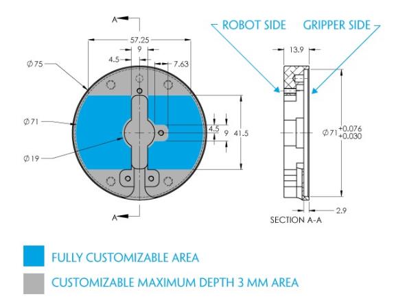
Fig. 6-5: Blank coupling AGC-CPL-BLANK-002 workable area dimensions.
Bolt pattern for coupling GRP-CPL-062 (refer to the Spare Parts, Kits and Accessories section) is compatible with :

Fig. 6-6: Coupling for ISO 9409-1-50-4-M6.
Bolt pattern for coupling GRP-CPL-063 (refer to the Spare Parts, Kits and Accessories section) is compatible with :

Fig. 6-7: Coupling for ISO 9409-1-31.5-4-M5.
Bolt pattern for coupling GRP-CPL-064 (refer to the Spare Parts, Kits and Accessories section) is compatible with :
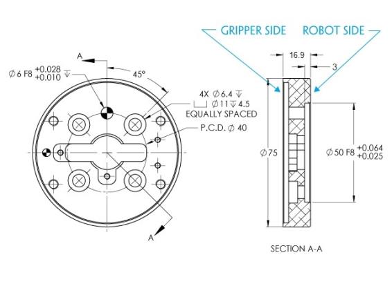
Fig. 6-8: Coupling for ISO 9409-1-40-4-M6.
Bolt pattern for coupling AGC-CPL-065-002 (refer to the Spare Parts, Kits and Accessories section) is compatible with :
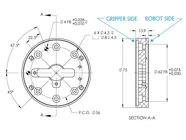
Fig. 6-9: Coupling for PCD 56 mm with 8 x M4 clearance.
Info
Although coupling AGC-CPL-065-002 is compatible with 8 x M4 threads on a 56 mm PCD it uses only 6 of the 8 normally present holes.
Bolt pattern for coupling AGC-CPL-066-002 (refer to the Spare Parts, Kits and Accessories section) is compatible with:
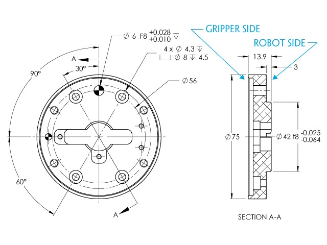
Fig. 6-10: Coupling for PCD 56 mm with 6 x M4 clearance.
Bolt pattern for coupling AGC-CPL-067-002 (refer to the Spare Parts, Kits and Accessories section) is compatible with :
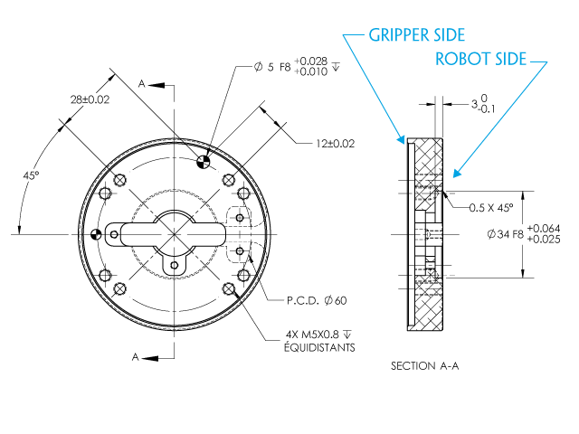
Fig. 6-11: Coupling for PCD 60 mm with 4 x M5 clearance.
Bolt pattern for coupling AGC-CPL-068-002 (refer to the Spare Parts, Kits and Accessories section) is compatible with :
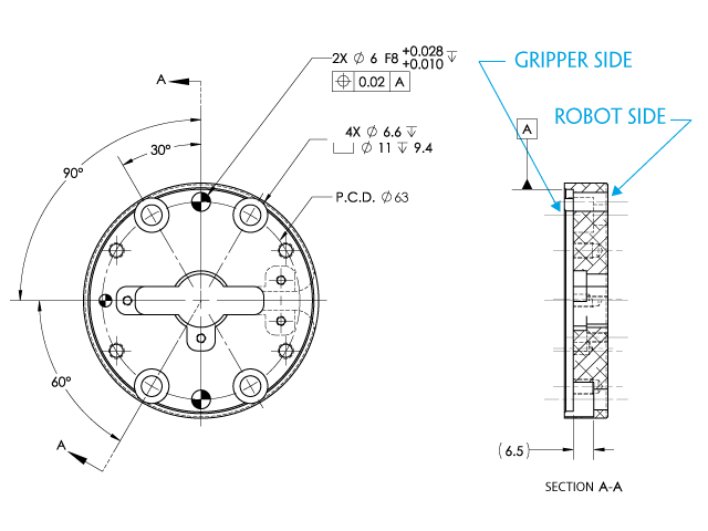
Fig. 6-12: Coupling for PCD 63 mm with 6 x M6 clearance.
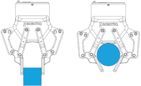
The contact grasp points for the Robotiq 2-Finger Adaptive Robot Gripper are its two fingertip pads and palm pad. Many fingertips are available from Robotiq (refer to the Spare Parts, Kits and Accessories section). The user can customize their own fingertips from blanks or create them from scratch. The figure below represents the distal phalanx (which acts as the fingertip holder) the permanent, non customizable part of the Gripper finger on which the fingertip must be mounted.
Custom fingertip designs must abide by the following:
Info
Both 2-Finger 85 and 2-Finger 140 use the same fingertips and finger holder.
![]()
Fig. 6-13: Distal phalanx for holding standard or custom fingertips.
Tip
Custom fingertips will still be subject to the equilibrium line rule for proper actuation of the Gripper, see General Presentation section.
The figure below represents a flat silicone fingertip AGC-TIP-204-085 (2F-85) and AGC-TIP-420-140 (2F-140); please refer to the Spare Parts, Kits and Accessories section. This fingertip has a flat silicone surface with an optimal friction coefficient for picking objects while the other surface will mount onto the fingertip holder shown in the Fingertips section.
![]()
Fig. 6-14: Flat silicone fingertip AGC-TIP-204-085

Fig. 6-15: Flat silicone fingertip AGC-TIP-420-140
The figure below represents the available grooved fingertip AGC-TIP-205-085 (2-Finger 85) and AGC-TIP-421-140 (2-Finger 140); please refer to the Spare Parts, Kits and Accessories section. This fingertip has a grooved surface with an optimal shape for picking cylindrical objects (with its horizontal and vertical grooves) while the other surface will mount onto the fingertip holder shown in the Fingertips section.

Fig. 6-16: Grooved fingertip AGC-TIP-205-085

Fig. 6-17: Grooved fingertip AGC-TIP-421-140
|
Specification |
2-FINGER 85 |
2-FINGER 140 |
|||
|---|---|---|---|---|---|
|
Metric Units |
Imperial Units |
Metric Units |
Imperial Units |
||
|
Gripper Opening |
85 mm |
3.35 in |
140 mm |
5.5 in |
|
|
Minimum object diameter (for encompassing) |
43 mm |
1.69 in |
90 mm |
3.5 in |
|
|
Maximum height |
162.8 mm |
6.4 in |
232.8 mm |
9.15 mm |
|
|
Maximum width |
148.6 mm |
5.85 in |
202.1 mm |
8.0 in |
|
|
Weight |
925 g |
2.04 lbs |
1,025 g |
2.25 lbs |
|
|
Grasp Force |
20 to 235 N |
4.5 to 52.8 lbf |
10 to 125 N |
2.2 to 28.1 lbf |
|
|
Finger speed |
20 to 150 mm/s |
0.8 to 5.9 in/s |
30 to 250 mm/s |
1.2 to 9.8 in/s |
|
|
Position repeatability1 |
0.05 mm |
0.002 in |
0.08 mm |
0.003 in |
|
|
Force repeatability |
+/- 10% |
||||
|
Position resolution2 |
0.4 mm |
0.016 in |
0.6 mm |
0.022 in |
|
|
Grasp force resolution |
Maximum force calculation below; refer to the Force control section |
||||
Info
All specs are measured with coupling GRP-CPL-062 and fingertip AGC-TIP-204-085 (2-Finger 85) or AGC-TIP-420-140 (2‑Finger 140).
1Repeatability is defined as the positional deviation resulting from the average displacement determined when picking an object with a parallel grasp using standard silicone fingertips. For more details see the blog.robotiq.com article on repeatability. Position repeatability varies depending on the product wear and operating conditions. The presented values are typical for the newly-manufactured products.
2Resolution is the increment modified from a 1 bit difference of position/speed/force request (from 0 to 255).
Actuation force model used to calculate recommended payload is described in the figure below, the user must not exceed the force and torque limits:

Fig. 6-18: Actuation force on the fingertip of the Adaptive Gripper 2-Finger (see charts below for 2-Finger 85 and 2-Finger 140 force).
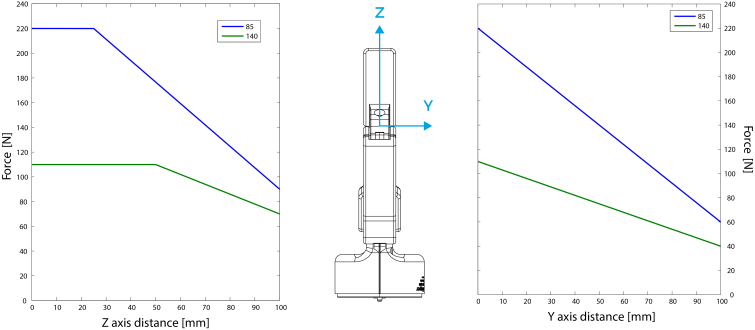
Fig. 6-19: Grasp force in the Y and Z axis for the 2-Finger 85 and 2-Finger 140.
Info
Info
The user of the Gripper must always ensure that the result of the forces against the finger is always lower than the maximum holding force as seen in figure 6-18.
As defined in figure 6-18, the weight that can be lifted is defined by :
Info
For example, if the silicone fingertips AGC-TIP-204 are used to lift a lubricated steel object (machine tending with cutting oils), the friction coefficient would be 0.3 (tested static coefficient of friction).
Maximum weight with a safety factor of 2.4 would be :
W = (2 x 200 N x 0.3) / 2.4 = 50 N
This calculation means that a 5 kg object will be held by the Gripper when not moving (standing still). When accelerating, the payload will decrease.
For example, if your robot accelerates at 2g then the 5 kg object would weigh 100 N and would therefore be dropped.
The biggest factor in such calculations will always be the friction coefficient, we recommend testing the coefficient.
Warning
You must consider the robot acceleration in your payload calculations.
Robot emergency stops will lead to major deceleration velocities.
|
Grasp Type |
2F-85 |
2F-140 |
|---|---|---|
|
Friction grasp |
5 kg |
2.5 kg |
|
Form-fit grasp |
5 kg |
2.5 kg |
Equilibrium line position (explained in the General Presentation section) is detailed in the figure below, where:
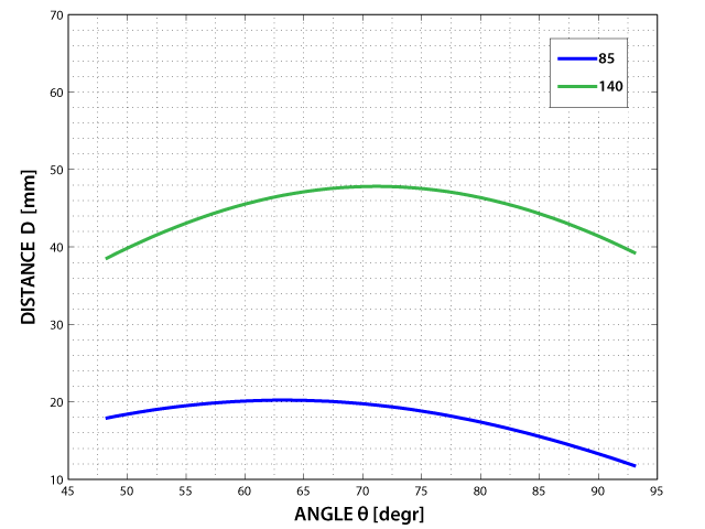
Fig. 6-20: Position of the Gripper equilibrium line according to the opening angle for 2-Finger 85 and 2-Finger 140 options.
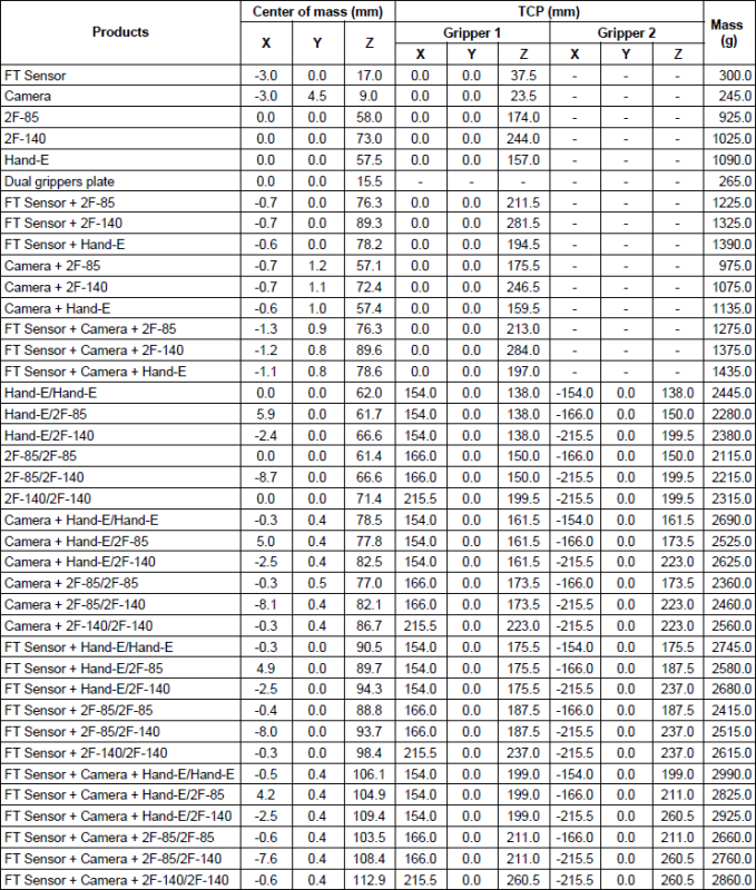
Coupling is included when Gripper is not mounted on the Camera. Dual Gripper adapter plate included where appropriate.
Info
The angle to calculate the TCP for Grippers mounted on a dual gripper assembly is as follows:
The moment of inertia are calculated for a configuration where the fingers are fully open. Here is the approximate moment of inertia matrix for the Gripper:
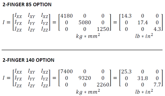
Fig. 6-21: Robotiq 2-Finger inertia matrix.
The 2-Finger Adaptive Gripper has maximum moments and force limit. The listed moments and forces are independent to the force applied by the Gripper itself on it's payload. For payload calculation, refer to the Mechanical specifications section.
Warning
The following limits must be respected at all time. Calculation of maximum moment and force should include the robot acceleration and a safety factor.
|
Parameters |
Finger Option |
|
|---|---|---|
|
2-Finger 85 |
2-Finger 140 |
|
|
Fx, Fy, Fz |
50 N |
25 N |
|
Mx* |
5 Nm |
5 Nm |
|
My* |
5 Nm |
5 Nm |
|
Mz |
3 Nm |
3 Nm |
* Moments in x and y are calculated from the base of the fingertips as shown in figure 6-19.
Example usage of the listed limit :
|
SPECIFICATION |
VALUE |
|---|---|
|
Operating supply voltage |
24 V DC ±10% |
|
Absolute maximum supply voltage |
28 V DC |
|
Quiescent power (minimum power consumption) |
< 1 W |
|
Peak current |
1 A |