The following sections provide data on the various specifications of the Robotiq Force Torque Sensor.
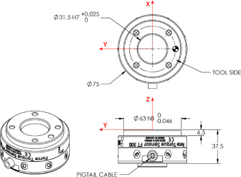
Fig. 5.1: Robotiq FT 300 Sensor general technical dimensions.
Info
Reminder: Measures are in millimeters.
The figure below illustrates the bolt pattern used for tool fixation on the FT 300 Sensor.
Info
FT 300 tool side bolt pattern matches ISO-9409-1-50-4M6.

Fig. 5.2: FT 300 Sensor tool side bolt pattern.
Info
Reminder: all units are within the metric measurement system.
|
SPECIFICATION |
VALUE |
||
|---|---|---|---|
|
Approximate weight |
300 g |
||
|
Overload capacity |
A combined load exceeding 500% of the measuring range will permanently damage the Force Torque Sensor |
||
|
Outside diameter |
75 mm |
||
|
Thickness |
37.5 mm |
||
|
IP rating |
431 |
||
|
Stiffness |
Fx, Fy |
35 X 106 N/m |
|
|
Fz |
30 X 106 N/m |
||
|
Mx, My |
10,000 Nm/rad |
||
|
Mz |
20,000 Nm/rad |
||
1Expected rating, certification is planned and will be forthcoming (see manual revision date).
The coordinate system used for calculating the moment of inertia and center of mass for the FT Sensor is shown in the figure below.
Info
All values are approximate. Actual coordinates may vary according to various options present on the Sensor.
Here is the approximate position of the center of mass for the FT Sensor:
|
Sensor |
Combination |
x (mm) |
y (mm) |
z (mm) |
Mass (g) |
|---|---|---|---|---|---|
|
FT 300 |
- |
0 |
0 |
17 |
300 |
|
2-Finger 85 |
0 |
0 |
76 |
1205 |
|
|
2-Finger 140 |
0 |
0 |
83 |
1275 |
|
|
Wrist Camera |
0 |
2 |
30 |
530 |
|
|
Wrist Camera and 2-Finger 85 |
0 |
1 |
77 |
1275 |
|
|
Wrist Camera and 2-Finger 140 |
0 |
1 |
85 |
1340 |
Here is the approximate moment of inertia matrix for the FT Sensor, taken at the coordinate system origin:

Fig. 5.3: Moment of inertia of the FT 300 Sensor.
The FT 300 sensors have overload capacities, the overload capacity specification includes load and torque values in all 3 axes.
Info
For loads between the measuring range and the overload capacity, the signal will be saturated. The sensor will not undergo permanent damage if the overload capacity is not reached.
Warning
Exceeding the overload capacity will permanently damage the sensor.
|
Sensor |
Measuring range |
Overload capacity1 |
|---|---|---|
|
FT 300 |
+/- 300 N |
1500 N (500%)2 |
1Overload capacity with all axes combined.
2Maximum load expressed in % of measuring range.
The overload capacity given includes forces and torques in all 3 axes. To get an approximation of the total load, these formulas must be used:
Fx/300 + Fy/300 + Fz/300 + Mx/30 + My/30 + Mz/30 < 500%
|
SPECIFICATION |
FT 300 (prior to 10/2017) |
FT 300 |
|
|---|---|---|---|
|
Measuring range |
Force |
±300 N |
|
|
Torque |
± 30 Nm |
||
|
Signal noise* |
Fx, Fy |
1.2 N |
0.1 N |
|
Fz |
0.5 N |
0.1 N |
|
|
Mx, My |
0.02 Nm |
0.005 Nm |
|
|
Mz |
0.03 Nm |
0.003 Nm |
|
|
Recommended threshold when mounted on a robot |
Fx, Fy |
5 N |
1 N |
|
Fz |
2 N |
1 N |
|
|
Mx, My |
0.08 Nm |
0.02 Nm |
|
|
Mz |
0.12 Nm |
0.01 Nm |
|
|
External noise sensitivity** |
Immune |
||
|
Data output rate |
100 Hz |
||
|
Temperature compensation*** |
15 to 35 °C |
||
*Signal noise is the standard deviation of the signal measured over a period of one (1) second
**Under normal operating conditions
***Within this range, the temperature fluctuation is compensated for; signal quality may be affected outside of this range
Caution
The recommended threshold represents the smallest variations that can be detected by the sensor.
The signal noise is the limiting factor for the Sensor's precision.For the FT 300, the signal noise defined in the signal specifications is the standard deviation of each data (Fx, Fy, Fz, Mx, My, Mz) over 1 second. In order to use that signal noise information, three times the standard deviation given must be used. According to the normal distribution, three times the standard deviation will cover almost all values possible (99.7%).
Info
Noise is an unwanted and unpredictable alteration to a signal. It may come from electrical or electromagnetic sources and degrades the quality of the Sensor's signal.
|
SPECIFICATION |
VALUE |
|---|---|
|
Input voltage |
5 to 24 V DC ± 10% |
|
Max power consumption |
2 W |
|
Communication electrical interface |
RS-485 |
|
Recommended fuse |
Phoenix #0916604 (UT6-TMC M 1 A) |
|
Recommended power supply |
TDK-Lambda DPP Series 15W Single Output DIN Rail Mount Power Supply, DPP15-24 |
For a detailed list of available couplings and adapter plates, please refer to the Spare Parts, Kits and Accessories section.
The following subsections contain data required for custom couplings or creating couplings from blanks.
Info
All Robotiq couplings and adapter plates are provided with necessary hardware for fixation on the Robotiq device side.
Caution
Unless identified for specific packages only, robot side screws and indexing pins are not provided.
The figure below schematics represent the optional blank coupling for the FT 300 Sensor :
Warning
Make sure your custom design does not interfere with the M4 threads or the 63 mm, H8 centering circle.
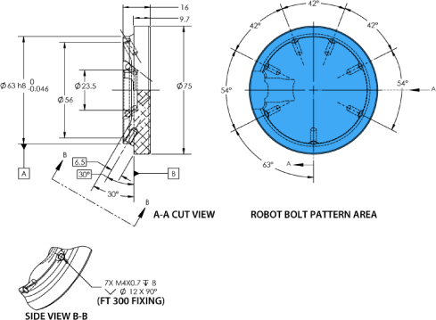
Fig. 5.4: Technical dimensions of the blank coupling for the FT 300.