Info
The following manual uses the metric system, unless specified, all dimensions are in millimeters.
The following sub-sections provide data on the various specifications for Hand-E.
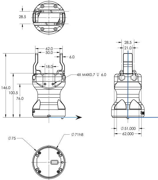
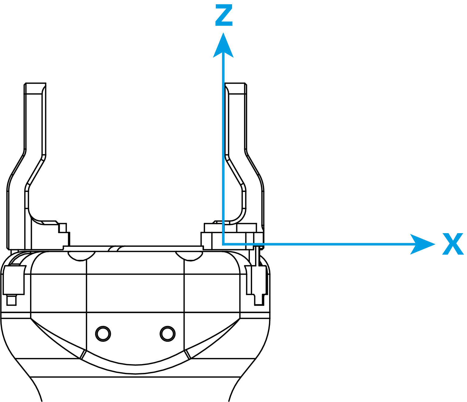
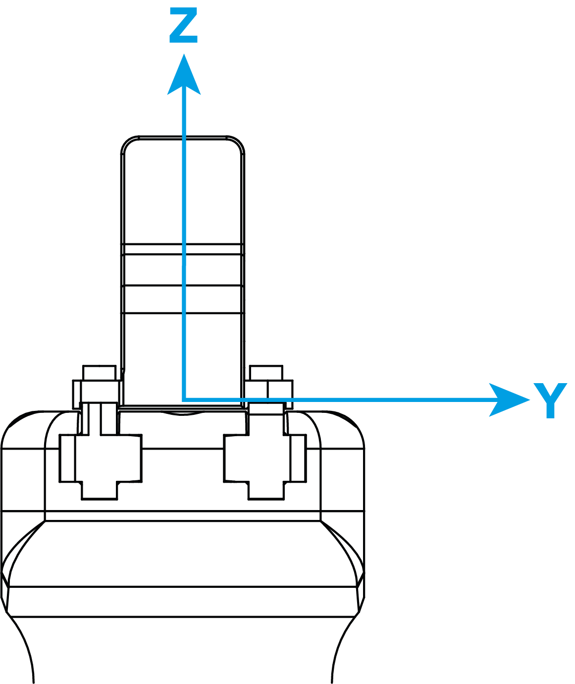
The figure below represents the Gripper's dimensions with axes X, Y, Z, and origin referenced for finger motion.
Info
All technical drawings in the present section are shown with the basic aluminum fingers.
Fig. 6-1: General dimensions of Hand-E (open)
Hand-E requires a coupling provided by Robotiq to operate.
The coupling is mandatory since it integrates electronics and electrical contacts.
Blank coupling
Below are the dimensions of the blank coupling, AGC-CPL-BLANK-002 (please refer to the Spare Parts, Kits and Accessories section), available to create a custom bolt pattern. The blue section can be fully customized (holes can be placed in any part of this section) while the grey section can only be worked to a depth of 3 mm.
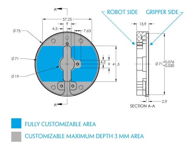
Fig. 6-2: Workable area dimensions of blank coupling AGC-CPL-BLANK-002
Coupling for ISO 9409-1-50-4-M6
Bolt pattern for coupling GRP-CPL-062 (please refer to the Spare Parts, Kits and Accessories section) is compatible with:

Fig. 6-3: Coupling for ISO 9409-1-50-4-M6.
Coupling for ISO 9409-1-31.5-4-M5
Bolt pattern for coupling AGC-CPL-063-002 (please refer to the Spare Parts, Kits and Accessories section) is compatible with:
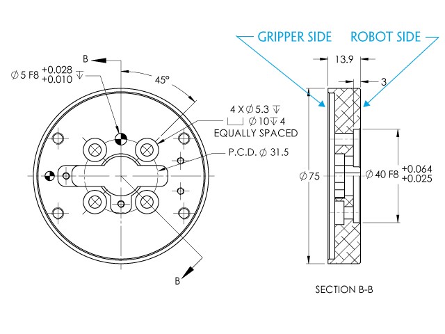
Fig. 6-4: Coupling for ISO 9409-1-31.5-4-M5.
Coupling for ISO 9409-1-40-4-M6
Bolt pattern for coupling AGC-CPL-064-002 (please refer to the Spare Parts, Kits and Accessories section) is compatible with:
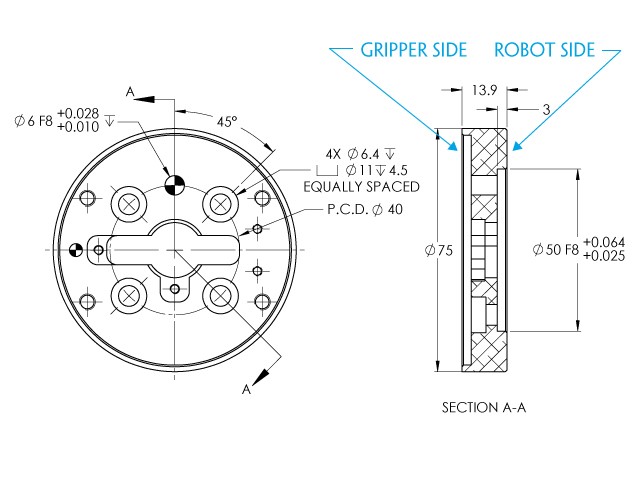
Fig. 6-5: Coupling for ISO 9409-1-40-4-M6.
Coupling for PCD 56 with 8 x M4
Bolt pattern for coupling AGC-CPL-065-002 (please refer to the Spare Parts, Kits and Accessories section) is compatible with:
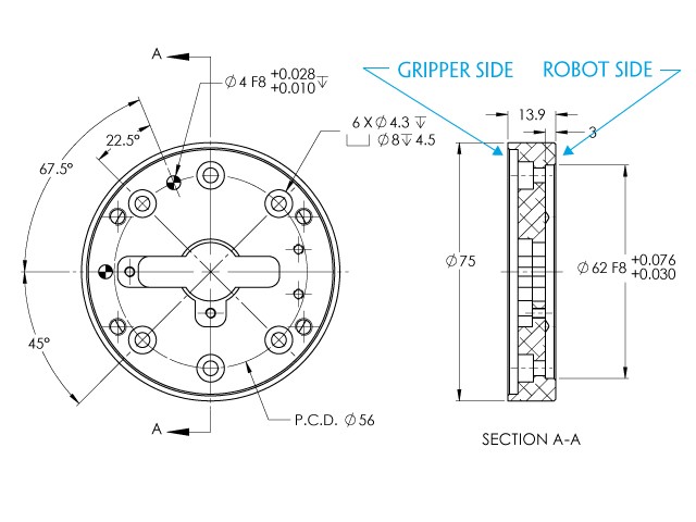
Fig. 6-6: Coupling for PCD 56 mm with 8 x M4 clearance.
Info
Although coupling AGC-CPL-065-002 is compatible with 8 x M4 threads on a 56 mm PCD it uses only 6 of the 8 normally present holes.
Coupling for PCD 56 with 6 x M4
Bolt pattern for coupling AGC-CPL-066-002 (please refer to the Spare Parts, Kits and Accessories section) is compatible with:
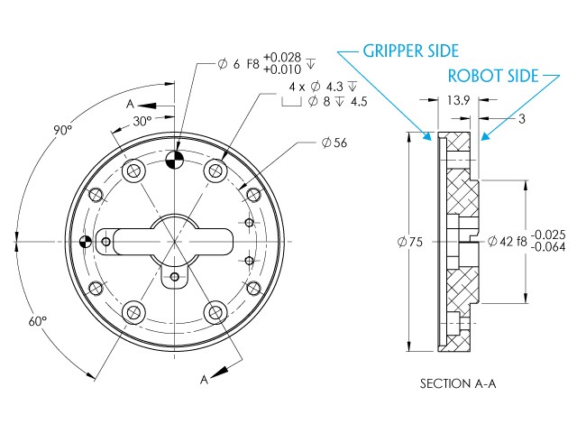
Fig. 6-7: Coupling for PCD 56 mm with 6 x M4 clearance.
Coupling for PCD 60 with 4 x M5
Bolt pattern for coupling AGC-CPL-067-002 (please refer to the Spare Parts, Kits and Accessories section) is compatible with:
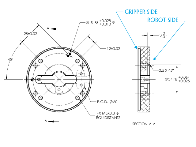
Fig. 6-8: Coupling for PCD 60 mm with 4 x M5 clearance.
Coupling for PCD 63 with 6 x M6
Bolt pattern for coupling AGC-CPL-068-002 (please refer to the Spare Parts, Kits and Accessories section) is compatible with:
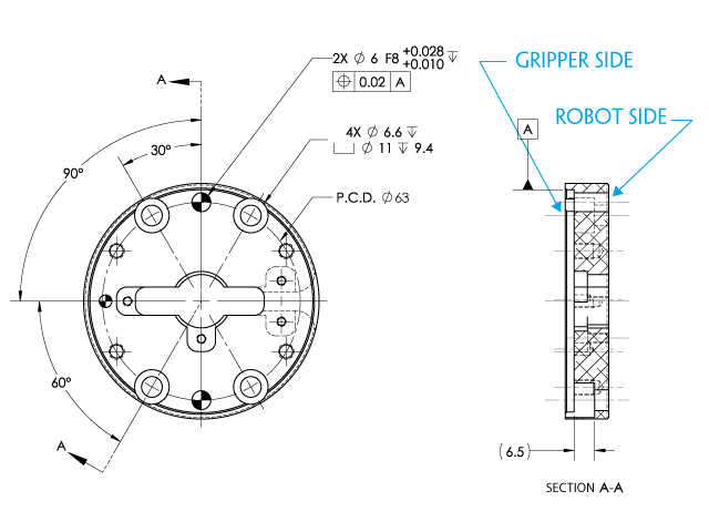
Fig. 6-9: Coupling for PCD 63 mm with 6 x M6 clearance.
The contact grip points for Hand-E are its two fingertip pads.
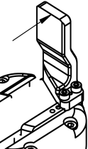
Fingertip options are supplied by Robotiq (please refer to the Spare Parts, Kits and Accessories section). Users can create their own fingertips from scratch. The figure below represents the fingertip holder, the permanent, non customizable part of the Gripper finger on which the fingertip must be mounted.
Custom fingertip design must meet the following specifications:
Warning
The following limits must be respected at all times.
Calculation of maximum moment and force should include robot acceleration and safety factors.
Info
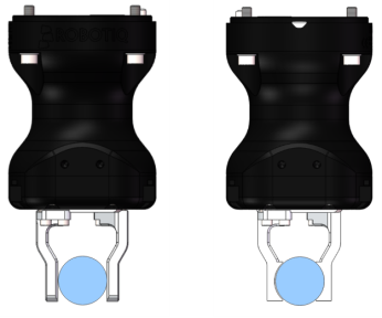
You can install custom fingertips directly on the rack or on the fingertip holder.
Tip
Fingertips can be mounted directly on the racks or on fingertip holders.
A finger is installed directly on a rack. You may customize your own fingers that will mount on this part. The basic aluminum fingers (HND-FIN-ALU-KIT) are mounted directly onto it.

|

|
Fig. 6-10: Racks in rack housing
The figure below represents the basic aluminum fingertip (HND-FIN-ALU-KIT); please refer to the Spare Parts, Kits and Accessories section. This finger allows a 0-50 mm stroke.

|

|

|
Fig. 6-11: Aluminum finger
In order to install fingertips on the racks, fingertip holders must be used (HND-TIP-HLD-KIT); please refer to the Spare Parts, Kits and Accessories section. You may customize fingertips to install directly on those. Both the flat silicone (HND-TIP-SLC-KIT) and V-groove fingertips , (HND-TIP-VGR-KIT) install on the fingertip holders.
|
|

|

|
Fig. 6-12: Fingertip holder
The figure below represents a flat silicone fingertip (HND-TIP-SLC-KIT); please refer to the Spare Parts, Kits and Accessories section. This fingertip has a flat silicone surface with an optimal friction coefficient for picking parts. This fingertip must be mounted on a rack using the fingertip holder (HND-TIP-HLD-KIT).

|

|

|

|
Fig. 6-13: Flat silicone fingertip
The figure below the available grooved fingertip (HND-TIP-VGR-KIT); please refer to the Spare Parts, Kits and Accessories section. This fingertip has a grooved surface with an optimal shape for picking cylindrical parts (by its horizontal and vertical grooves). This fingertip must be mounted on the racks using the fingertip holder (HND-TIP-HLD-KIT).

|

|

|

|
Fig. 6-14: Grooved fingertip
|
Specification |
Metric Units |
Imperial Units |
|
|---|---|---|---|
|
Gripper opening |
0 - 50 mm |
0 - 1.97 in. |
|
|
Maximum recommended payload |
5 kg |
11 lbs |
|
|
Maximum recommended payload, friction grip
|
3.3 kg |
6.6 lbs |
|
|
Gripper height (without fingertips) |
100.5 mm |
3.94 in |
|
|
Gripper diameter |
75 mm |
2.95 in |
|
|
Gripper weight (including coupling) |
1070 g |
2.3 lbs |
|
|
Grip force |
20 - 130 N |
4.5 - 27 lbf |
|
|
Finger speed |
20 to 150 mm/s |
0.8 to 5.9 in/s |
|
Info
All specs are measured with coupling GRP-CPL-062 and basic aluminum fingertips (HND-FIN-ALU-KIT).
Actuation force model used to calculate the recommended friction payload (W):
where:
![]()
Fig. 6-15: Actuation force on the fingertip of the Hand-E Gripper
Info
Info
For example, if the silicone fingertips (HND-TIP-SLC-KIT) are used to lift a lubricated steel part (machine tending with cutting oils), the friction coefficient would be 0.3 (tested static coefficient of friction).
Maximum weight with a safety factor of 2.4 and maximum force would be:
W = (2 x 130 N x 0.3) / 2.4 = 32.5 N
This calculation means that a 3.3 kg part will be held by the Gripper when not moving (standing still). When accelerating, the payload will decrease.
The biggest factor in such calculations will always be the friction coefficient, we recommend testing the coefficient.
Warning
You must consider the robot acceleration in your payload calculations.
Robot emergency stops will lead to major deceleration velocities.
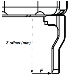
The maximum payload force recommended depends on the distance on the Z-axis at which the force/payload (F) is applied when using custom fingers on the Hand-E Gripper.
|
|
Fig. 6-16: Z-axis offset at which force/payload is applied (tip of the finger, in the middle of the inner surface)
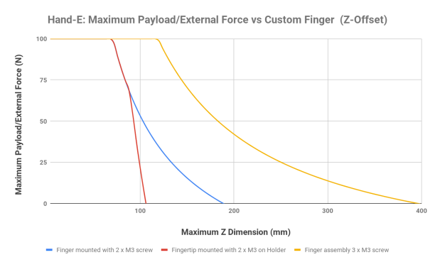
Fig. 6-17: Scheme Illustrating Maximum Payload/External Force vs. Z-Offset on Custom finger
Info
The data is calculated at the resulting position of the force applied, based on the strength of the M3 screws used. The maximum grasping force is included in the calculation; it represents the maximum force that can be added to the finger (payload force + external force).
Warning
Caution
In order to address other custom specific cases with regards to your own application, the main item to address is the strength of the screws used for mounting the fingers.
|
Grasp Type |
Maximum Payload |
|---|---|
|
Friction grasp |
3 kg |
|
Form-fit grasp |
5 kg |
Couplings are included when Grippers are not mounted on the Camera. Dual Gripper adapter plates are included where appropriate.
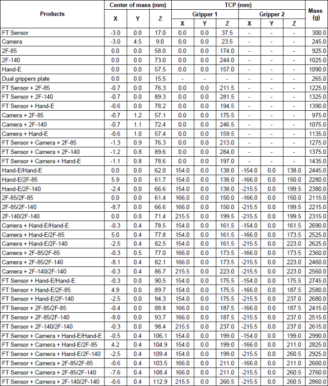
Info
The angle to calculate the TCP for Grippers mounted on a dual gripper assembly is as follows:
The coordinate system used to calculate the moment of inertia and center of mass of the Gripper is shown in the figure below.

Fig. 6-18: Inertia matrix for Hand-E
The Hand-E Gripper has limits for moment and force values. The maximum moment and force values are independent of the grasp force applied by the Gripper on its payload. For payload calculation, please refer to the Payload and force section.
Warning
The following limits must be respected at all times.
Calculation of maximum moment and force should include robot acceleration and safety factors.
|
Parameter |
Hand-E with Basic Aluminum Fingers |
|---|---|
|
Fx, Fy, Fz |
100 N |
|
Mx* |
2.65 Nm |
|
My* |
3.74 Nm |
|
Mz* |
2.00 Nm |
*Moments in x and y are calculated from the base of the fingers, as shown in the figure below.
|
|
Fig. 6-19: Reference frame for maximum force and moment values applied to the fingers
Usage examples with listed limits:
|
SPECIFICATION |
VALUE |
|---|---|
|
Operating supply voltage |
24 V DC ±10% |
|
Quiescent power (minimum power consumption) |
1 W |
|
Peak current |
1.1 A |