The following subsections will guide you through the installation and general setup of your Robotiq 2-Finger Adaptive Robot Gripper.
Warning
Before installing:
Warning
When installing:
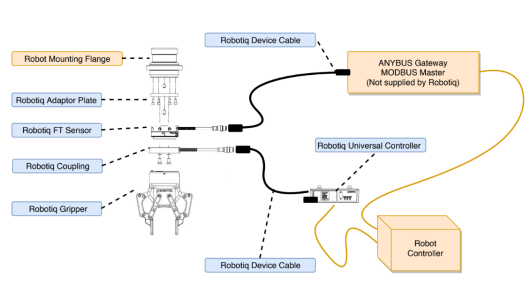
A gripper Kit generally includes these items:
Fig. 3-1: Schema of the required hardware.
Depending on the robot, an adapter plate might be available. Refer to the Couplings section in the Specifications section
Depending on the communication protocol available, the user might need an additional signal converter such as a USB to RS232 converter, for serial ports, or a Robotiq Universal Controller for ethernet based communication. The Universal Controller supports:
Info
The following are not included in standard delivery:
Info
When bought as a kit, the 2-Finger 85 or 140 will come in a package with the appropriate coupling, fingertips or finger pads and cabling. Please refer to the Spare Parts, Kits and Accessories section.
The following tools are required to install the 2-Finger Adaptive Gripper:
Optional tools if installing finger kits: AGC-FIN-KIT-085 or AGC-FIN-KIT-140:
Optional tools if installing other fingertips: AGC-TIP-204-085, AGC-TIP-205-085, AGC-TIP-420-140, AGC-TIP-420-140
The following parts are required for setup :
The Gripper needs to be supplied by a DC voltage source. This power supply is not included with the Gripper. Required power supply must match the Robotiq device. The following table shows the specifications with regards to the power supply required to operate the Gripper and the optional Robotiq Controller.
|
SPECIFICATION |
VALUE |
|---|---|
|
Output voltage |
24 V DC ±10% |
|
Output current |
1 A |
|
Overcurrent |
Recommended power supply with internal protection, otherwise fusing is required. 2 A fuse at 25°C [77°F]1 |
Table 3-1: 2-Finger power supply requirements.
Info
1 Suggested fuse is a: Phoenix Contact # 0916605 2 A thermal, use AWG #20 wiring.
Warning
If your power supply could exceed the specified regulation, over-voltage protection is required.
Robotiq recommends the use of the following power supplies:
Tip
Optional Robotiq Universal Controller can use the same power supply.
|
CONDITION |
VALUE |
|---|---|
|
Minimum storage/transit temperature |
-30°C [-22°F] |
|
Maximum storage/transit temperature |
70°C [158°F] |
|
Minimum operating temperature |
-10°C [14°F] |
|
Maximum operating temperature |
50°C [122°F] |
|
Humidity (non-condensing) |
20-80% RH |
|
Maximum vibration (storage/transit) |
5G |
|
Maximum vibration (operating) |
2G |
|
IP Rating |
IP 40 |
|
Other |
|
Table 3-2: Environmental and operating conditions of the 2-Finger Adaptive Gripper
Depending on your order, you may or may not have fingers already mounted on the Gripper. The first step of installation should be to install the fingers. Refer to the figure below for finger placement. To do so :

Fig. 3-2: 2-Finger Adaptive Gripper installation.
Depending on your options, you may have fingertips to install. The second step of the installation should be to install the fingertips. To do so:

Fig. 3-3: Installing the fingertips on the Gripper
An optional protector kit (AGC-PRO-KIT-V4) can be ordred to cover the fingers of the 2F-85 and therefore protect users and assets against pinch points.
You can install them using eight (8) M3 screws.
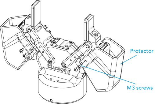
Fig. 3-4: Protector Kit Installation
You must use a coupling to attach the Gripper to the robot. Be sure to use the coupling related to your robot model. If there is no coupling for your robot, you can modify a blank coupling or Robotiq can create a custom version for you. Some couplings may require an additional adapter plate. To create your own coupling or adapter plate you can refer to the Coupling section. To see the details of the available couplings and adapter plates, please refer to the Spare Parts, Kits and Accessories section.
Here are the steps to follow to mount the Gripper to your robot (exploded view in the figure below). Note that all screws must be locked in place using medium strength threadlocker.

Fig. 3-5: Installing the Gripper to a robot using an adapter plate and coupling.
When installing multiple grippers on one robot, every gripper must have its own coupling.

Fig. 3-6: Exploded View of a Dual Gripper Setup
Power and communication are established with the 2-Finger Adaptive Robot Gripper via a single Device Cable. The Device Cable provides a 24V power supply to the Gripper and enables serial RS485 communication to the robot controller. An optional Robotiq Universal Controller may be used between the Gripper and the network / robot controller if fieldbus communication is required.
Info
RS485 signals (485+, 485- and 485 GND) are isolated from the main 24V power supply. 4 GND can be connected to any other ground reference as long as the voltage potential between the grounds does not exceed 250V. Grounding reference is at the user's discretion.
Gripper grounding is optional and is done via the robot ground. The coupling indexing pin (dowel) is the ground connector. Gripper coupling, chassis and proximal phalanx are linked as illustrated in the figure below. They link through the coupling indexing pin to the robot ground. Proximal bars, distal phalanx, fingertip base and fingertips are isolated.
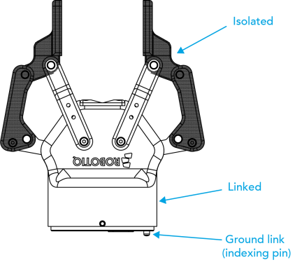
Fig. 3-7: Robotiq 2-Finger electrical isolation / grounding.
The Gripper interfaces with its coupling via a 10-spring pin connector located on its outer surface.

Info
The coupling used in the figure above is used for reference only and corresponds to bolt pattern ISO 9409-1-50-4-M6.
If a Robotiq Universal Controller is used, please refer to the Robotiq Universal Controller manual. The figure below represents the wiring schematic of the 2-Finger with device cable, power supply, fuse (please refer to the Required Tools and Equipment section) and grounding.
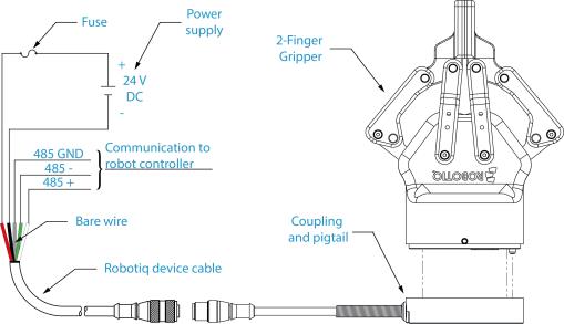
Fig. 3-8: Robotiq 2-Finger with pigtail cable and device cable wiring schematic.
Warning
Use proper cabling management. Be sure to have enough forgiveness in the cabling to allow movement of the Gripper along all axes without pulling out the connectors. Always protect the controller-side (robot side) connector of the cable with a strain relief cable clamp.
The figure below represents the 2-Finger pigtail connector from the coupling (AGC‑CPL‑XXX), device cable - robot side (CBL‑COM‑2065‑XX) and their associated pinout.
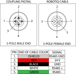
Fig. 3-9: Pinout of the 2-Finger pigtail and device cable.
If additional cable is used, suggested cable specifications are as follows:
Power supply, fusing:
RS485 signals :
Prior to any software installation or communication setup on the robot, connect the white, green, and bare wires to the proper signal converter required (RS485-USB, RS85-RS232, Robotiq Universal Controller). Also connect the red (24V) and black (0V) wires to the power supply.
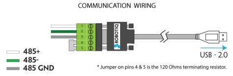
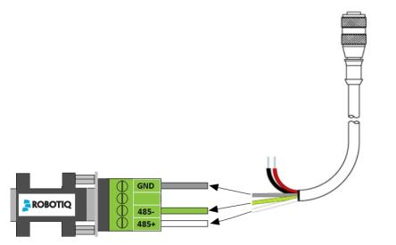
Fig. 3-10: 2-Finger Adaptive Robot Gripper wiring to signal converter
For connection on the Robotiq Universal Controller, please refer to the Robotiq Universal Controller Manual.
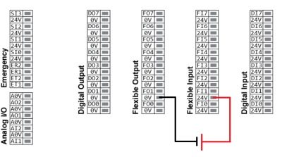
It is possible for some robots to communicate with more than one gripper at once by having grippers with different IDs. It requires a M12 splitter which is used to split the signal into two different grippers. Use the M12 splitter (AGC-SPLIT-M12-2:1) to connect the two grippers to the 10m cable (CBL-COM-2065-10-HF) which gets connected to the appropriate signal converter.
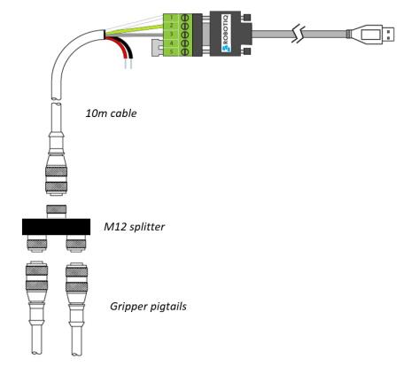
Fig. 3-11: Multiple grippers wiring
Once installed and properly secured, your Robotiq 2-Finger Adaptive Gripper should be tested with the Robotiq User Interface test software using the provided USB converter. To do so:
Info
The Activate command will initiate movement of the Gripper for auto-calibration procedures. Do not interfere with the Gripper. Be sure you have satisfied robot safety measures.
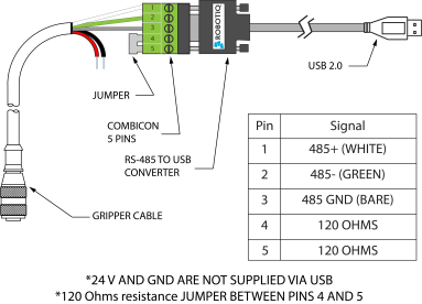
Fig. 3-12: RS-485 to USB converter ACC-ADT-USB-RS485 pinout.
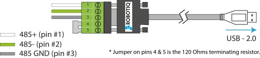
Fig. 3-13: Wiring of the USB to RS-485 converter.
Tip
With the R.U.I. controlling the Gripper, you can go to the "view" menu to see input and output register values to further your understanding on how to command the Gripper. You can also test grasping objects with various speed and force settings. See the Control section for details.
The following sections present the information regarding the proper plugin management through the system.
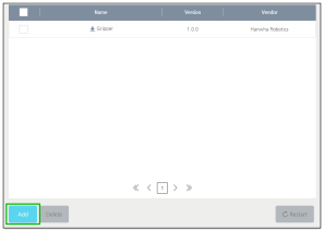
Fig. 3-14: Plugin management menu with Add button highlighted.
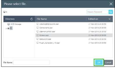
Fig. 3-15: Selection of the plugin with the OK button highlighted.
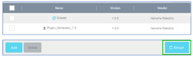
Fig. 3-16: View of the installed plugin with the Restart button highlighted.
Info
To install the plugin, you must be logged in as an administrator.
Info
When the plugin is correctly installed, it appears in the Management Menu. Restart the system should you want newly-installed plugins to be visible in the Management Menu.
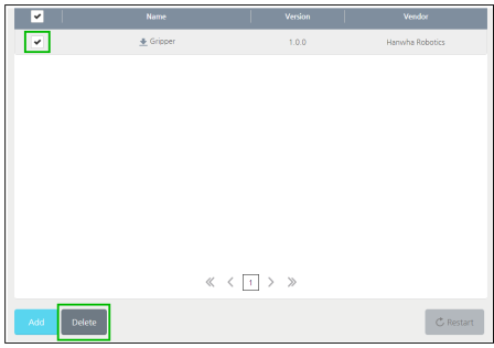
Fig. 3-17: Plugin Management menu with check box and Delete button highlighted.